25
A1
A21
2
3 4
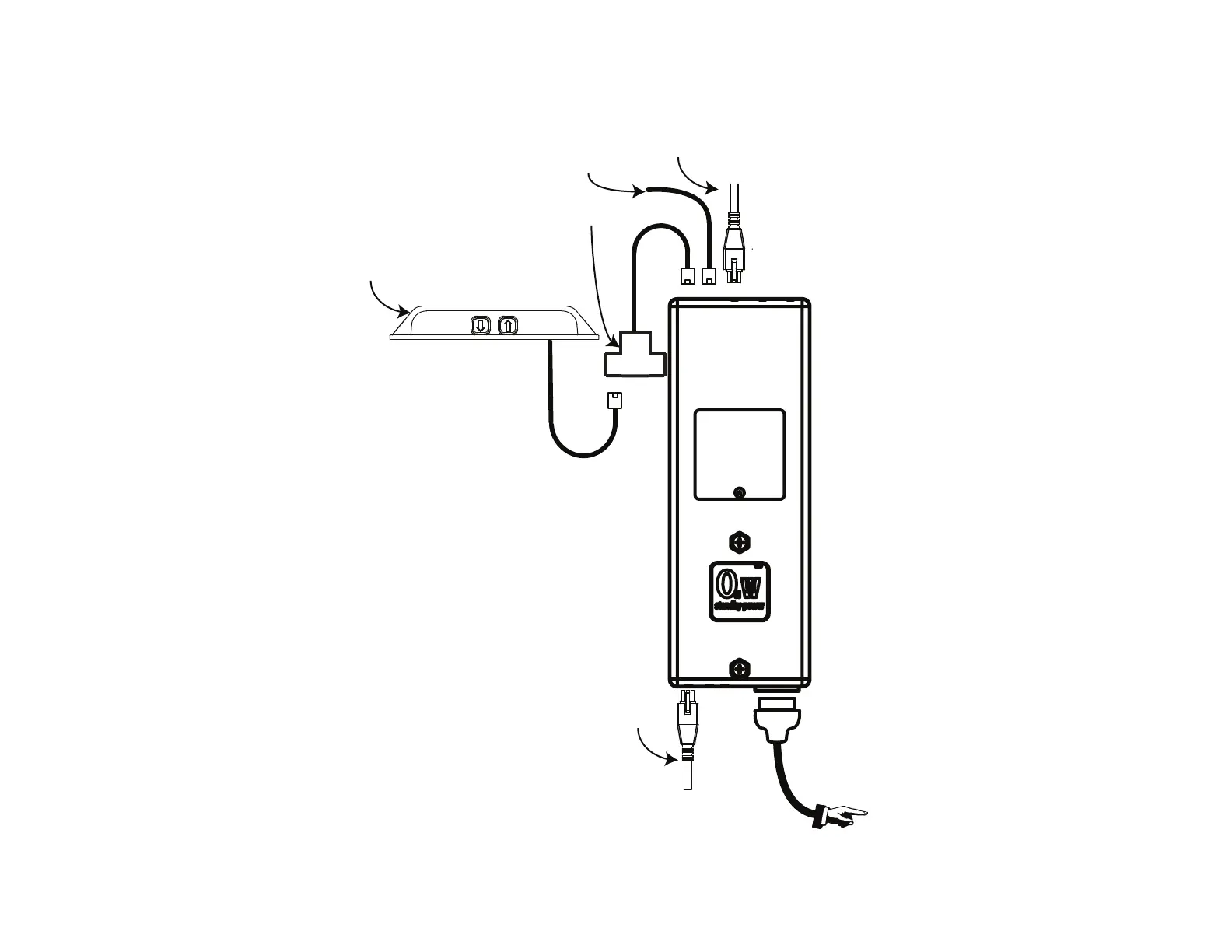
DC AC
To Power Outlet
Top Motor - Port 1
RJ 45 Splitter
IR Receiver
Bottom Motor - Port 2
Collision Detection Module - Port A2
Wiring Diagram - IR Controls
14b. Connect your Cables according to the diagram that corresponds to your control type. RF and IP Controls can be found on the previous page.
Note: The Top Motor will use the shorter Motor Cable & the Bottom Motor will use the longer Motor Cable.
The lift will not operate unless all cables are plugged in according to this diagram.
 Loading...