The PXI/PXIe/PCI-5122 is a high-speed digitizer designed for use in various measurement and automation applications. This document serves as a getting started guide, providing essential information for installation, configuration, and basic operation of the device.
Function Description
The PXI/PXIe/PCI-5122 functions as an oscilloscope, capable of acquiring, controlling, analyzing, and presenting data. It is designed to integrate into PXI, PXI Express, and PCI systems, offering flexibility for different hardware setups. The device supports both interactive data acquisition through the NI-SCOPE Soft Front Panel (SFP) and programmatic control using the NI-SCOPE instrument driver.
The core function of the PXI/PXIe/PCI-5122 involves converting analog input signals into digital data, which can then be processed and analyzed by a connected computer system. It features multiple input channels (CH 0 and CH 1 for analog input) and an external analog trigger (TRIG) for precise synchronization of acquisitions. For advanced timing and synchronization, the device includes Sample clock input and Reference clock input (CLK IN), as well as Sample clock output and Reference clock output (CLK OUT). An AUX I/O port provides PFI 0 and PFI 1 lines for digital trigger input/output, with PFI 1 also supporting probe compensation.
The device's operation is managed through National Instruments software, primarily Measurement & Automation Explorer (MAX) for configuration and NI-SCOPE for data acquisition and analysis. The NI-SCOPE SFP provides a user-friendly interface that mimics a standalone oscilloscope, allowing users to visualize and control waveforms directly from their computer. For more complex or automated tasks, the NI-SCOPE API (Application Programming Interface) enables programmatic control using development environments like LabVIEW, LabWindows/CVI, and Microsoft Visual C/C++. This allows users to create custom applications tailored to specific measurement needs, configuring hardware, performing acquisitions, and implementing custom analysis and measurement options.
Usage Features
The PXI/PXIe/PCI-5122 offers several features to enhance its usability across different applications:
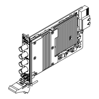
- Flexible Installation: The device is available in PXI, PXI Express, and PCI form factors, allowing integration into a wide range of chassis and computer systems. Installation involves physically inserting the module into a compatible slot and securing it. For PXI/PXIe modules, this includes ensuring proper seating in the module guides and latching with the ejector handle, followed by securing with front-panel mounting screws. PCI modules are inserted into expansion slots and secured to the computer back panel rail.
- Software Integration: The device relies on NI software for full functionality. The NI-SCOPE driver software is essential for operation, and an Application Development Environment (ADE) such as LabVIEW or LabWindows/CVI is required for programmatic control. MAX is used for initial configuration, device identification, and self-testing, ensuring the device is correctly recognized by the system.
- Interactive and Programmatic Control: Users can choose between interactive control via the NI-SCOPE SFP for quick measurements and visual analysis, or programmatic control using the NI-SCOPE API for automated tests, complex signal processing, and integration into larger systems. The NI-SCOPE SFP allows for immediate adjustments like auto-scaling the acquisition display.
- Synchronization Capabilities: The device supports synchronization with other instruments, particularly important in multi-device test setups. For PXI and PXI Express modules, this involves identifying the system controller in MAX. For PCI modules, an RTSI cable can be used to physically share triggers and clocks between devices, with configuration managed through MAX. For SMC-based devices, spread-spectrum clocking can be enabled in the PC BIOS to manage timing clock signals.
- Example Programs: To aid in application development, NI provides a variety of NI-SCOPE examples through the NI Example Finder. These examples serve as programming models and building blocks, demonstrating device functionality and helping users quickly develop their own applications in various ADEs.
- Front Panel Indicators: The front panel includes ACCESS and ACTIVE LEDs. The ACCESS LED indicates the status of the PCI bus and the interface to the controller, while the ACTIVE LED shows the status of the onboard acquisition hardware. These indicators provide immediate visual feedback on the device's operational state.
Maintenance Features
Maintaining the PXI/PXIe/PCI-5122 involves several considerations to ensure its longevity and optimal performance:
- Environmental Requirements: The device is designed for indoor use and has specific operating environment requirements for ambient temperature, relative humidity, maximum altitude, and pollution degree. Adhering to these conditions is crucial to prevent damage and ensure reliable operation.
- Electrostatic Discharge (ESD) Prevention: Proper handling procedures are emphasized to prevent ESD damage. Users are instructed to ground themselves before touching the device and to handle the module by its edges or metal bracket. Exposed pins of connectors should never be touched.
- Physical Inspection: Before installation, users should inspect the device for any loose components or signs of damage. Similarly, chassis backplane slot pins should be checked for bends or damage. Damaged modules should not be installed.
- Cooling and Airflow Management: Adequate cooling is vital for the device's performance and to prevent thermal shutdown errors. For PXI/PXIe systems, covering empty slots with EMC filler panels or slot blockers helps maximize cooling airflow. For PCI devices, leaving adjacent PCI slots empty can improve airflow and extend the device's life. Information on forced-air cooling is provided in a separate "Maintain Forced-Air Cooling Note to Users" document.
- Cleaning: The hardware should be cleaned with a soft, nonmetallic brush, ensuring it is completely dry and free from contaminants before returning it to service.
- Troubleshooting and Self-Test: The device includes built-in troubleshooting steps. If the ACCESS LED is off, users are guided to check power, inspect for damage, and try different chassis slots. MAX provides a self-test function to verify hardware resources. If the module fails the self-test or does not appear in MAX, steps include restarting the system, reinstalling the module, and checking device manager settings.
- Technical Support and Resources: National Instruments offers comprehensive worldwide support and services. Users can access troubleshooting guides, application development resources, email, and phone assistance through ni.com/support. Product registration at ni.com/register ensures users receive important updates. Information on NI Factory Installation Services, repairs, extended warranty, and calibration certificates is available at ni.com/services and ni.com/calibration, respectively. Declarations of Conformity (DoC) for electromagnetic compatibility (EMC) and product safety can be found at ni.com/certification.