Electrical connection
NOTE
All electrical connections must be carried out
by an authorised electrician.
Electrical installation and wiring must be carried
out in accordance with the stipulations in force.
EAH 20 must not be powered during installa-
tion.
NOTE
If the supply cable is damaged, only NIBE, its
service representative or similar authorised
person may replace it to prevent any danger
and damage.
The electrical circuit diagram is at the end of this Installer
manual.
SUPPLY
EAH 20 is connected to an earthed socket with the
factory-installed connection cable (length approx. 2,4
m), which is fitted with a plug.
Control signal is connected to X9:4 (230 V) and X9:3 (N)
on the accessory board (AA5) in NIBE ERS.
SENSORS
Use cable type LiYY, EKKX or similar.
1.
Disconnect the existing outdoor air sensor from
X2:15-16 on the accessory board (AA5) in NIBE ERS.
2.
Connect the enclosed outdoor air sensor (BT23) to
the same position.
24 20212223 1516171819 1314
BT23
AA5-X2
External
NIBEERS
Commissioning and
adjusting
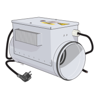
EAH 20 is installed in the outdoor air duct and, in cold
weather, heats the incoming outdoor air a few degrees
to prevent the heat exchanger freezing on the exhaust
air side. For further safety, in really cold weather, the
supply air fan will slow down in stages for the same
reason.
The output is set by changing the clamp connections
that are connected in the junction box, see wiring dia-
gram.
The output of EAH 20 is selected taking into considera-
tion the size of the house, any building regulations, and
the outdoor temperature at which the supply air fan is
permitted to start to slow down.
Caution
The energy saving is greater the lower the
output of EAH 20 that is selected. However,
this increases the outdoor air flow that enters
the house via leakage (instead of through the
heat recovery unit) at low outdoor temperat-
ures.
OUTPUTS
The diagram shows the temperature increase of the
outdoor air provided by EAH 20.
Output
0
5
10
15
25
20
30
35
40
Temperaturhöjning
(K)
Tilluftsflöde
(l/s)
300 W
1800 W
1200 W
900 W
600 W
1500 W
0 25 50 75 100 125 150
175
Temperature increase
Airflow
Service
After one year of operation it is recommended that the
following be checked:
• Ceramic connection isolators must be undamaged.
• The heating element's insulation resistance:
Connect the insulation tester to a ground connection
and one of the phases L1.1 / L1.2. If the measured
value is less than 20 Mohm, each separate heating
element must be checked. The minimum insulation
value is 50 Mohm at 1 000 V.
NIBE EAH 20-1800 | GB8
 Loading...