General
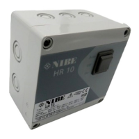
Auxiliary relay HR 10 is a junction box containing a con-
tactor and a rotary switch. It is used to control external
1 to 3 phase loads such as oil burners, immersion heat-
ers and pumps.
HR 10 can be set to three positions via the rotary switch:
• In ”Off” the load is disconnected.
• In ”On” the load is connected.
• In ”Auto” the load is controlled via external control
signal.
Auxiliary relay HR 10 can control up to 16 A and 400
VAC at resistive load.
Connection
NOTE
All electrical connections behind covers se-
cured by screws must be carried out by an
authorised electrician.
Electrical installation and wiring must be carried
out in accordance with the stipulations in force.
Use suitable screwdriver.
Install the enclosed unions in suitable positions. If the
outer diameter of the cable is not 10–13 mm, replace
the enclosed unions with others that are suitable for the
outer diameter of the cable.
CONNECT THE POWER SUPPLY TO
CONTACTOR -K1 AS FOLLOWS:
L1 to -K1:1, L2 to -K1:3, L3 to -K1:5
and N to -K1:13.
At 3 phase load:
L1 to -K1:1 and N to -K1:13. (Voltage
between -K1:1 and -K1:13 must be
230 VAC.)
At 1 phase load:
CONNECT THE LOAD TO CONTACTOR -K1
AS FOLLOWS:
L1 to -K1:2, L2 to -K1:4, L3 to -K1:6
and N to -K1:14.
At 3 phase load:
L1 to -K1:2 and N to -K1:14.At 1 phase load:
EXTERNAL CONTROL SIGNAL MUST BE
CONNECTED AT 230 VAC TO TERMINAL
BLOCK -X1:1 (PHASE) AND -X1:2 (N).
The electrical circuit diagram is at the end of this Installer
handbook.
5HR 10 | GB
English
 Loading...