5
GB
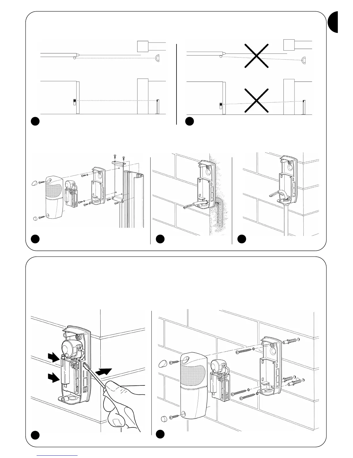
• The FT210 TX transmitter emits a beam with an angle of approximately ±4°, therefore a perfect alignment between TX and
RX is necessary that remains intact throughout the entire course of the gate.
Figure 4 illustrates an example of correct assembly; figure 5 illustrates two examples of incorrect assembly.
• If necessary, the receiver can be fitted on a special MOCF post with related FA2 accessories (see figure 6), or fixed to the
wall. In this case the cables can arrive from the base (see figure 7) or below, in which case it is necessary to use “PG9” type
cable clip (see figure 8).
3.2) Fixing of the devices
Perform the installation and fixing of the devices following the operations below:
1. To separate the control unit from the base, use a screwdriver to lever the three clips as indicated in fig. 9
2. Fix the receiver as shown in fig. 10.
4 5
6 7 8
9
10