8
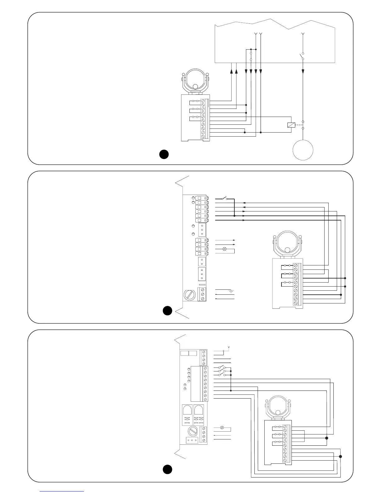
3.3.1) General connection example
Figure 18 shows a connection example of the
FT210 to a general control unit with PHOTO input;
ALT has a Phototest output. In this configuration,
set the RX jumpers as follows:
• JP1 connected
• JP2 activated, if activation of the ALT input of
the control unit causes shutdown and
inversion of movement (in this way the relay
connected to ALT1 in figure 18 can be
eliminated and the contact of ALT1 can be
placed in series to PHOTO and connected
to the PHOTO input of the control unit as
shown in figure 19 and 20)
deactivated, if activation of the ALT input
of the control unit causes only shutdown of
movement
3.3.2) Connection example with “Pho-
totest” equipped control unit
Figure 19 shows a connection example of the
FT210 to the ROBO “RO300” model gearmotor
with the use of the Phototest function. In this con-
figuration, set the RX jumpers as follows:
• JP1 connected
• JP2 connected (control unit with inversion of
movement on activation of ALT input
3.3.3) Connection example with “SCA”
equipped control unit
Figure 20 shows a connection example of the
FT210 to the ROBO “RO1000” model gearmotor
with the use of the SCA output.
In this configuration, set the RX receiver jumpers
as follows:
• JP1 disconnected
• JP2 activated (control unit with inversion of
movement on activation of ALT input)