LP21/LP22
LP21/LP22 Quick start guide 1.1 EN 3|4
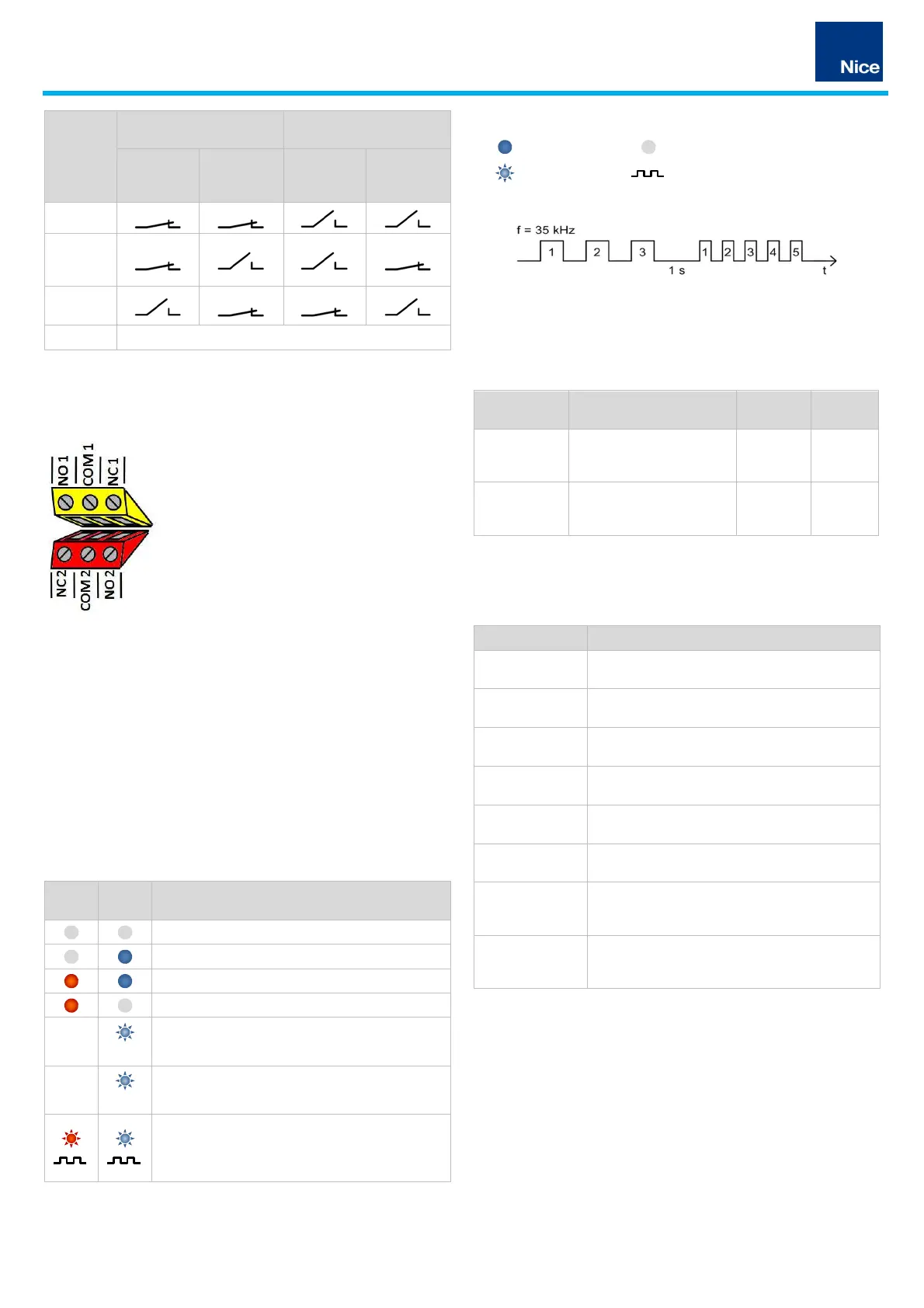
Sensors
Status
Normally closed contact
(NC)
Normally open contact
(NO)
Open circuit
current
Closed
circuit
current
Open circuit
current
Closed
circuit
current
Voltage off
Detector
ready,
loop free
Loop
covered
Loop fault (default: loop covered)
Tab. 4: Relay switch status
The analogue outputs of the relay versions (-R24) are connected to the
red and yellow terminal blocks as shown in the following illustration.
NO 1/2
Normally open contact to output 1
or output 2
COM 1/2 Common contact to output 1 or
output 2
NC 1/2 Normally closed contact to output 1
or output 2
Fig. 4: Relay connection 1 (yellow) and 2 (red)
4 Description of functions
4.1 LED status indicators
The LEDs (light emitting diodes) on the front side display the state of the
loops and the detector.
There is a blue and red LED for each loop channel:
• the red LED provides information on the loop state
• the blue LED provides information on the detector state
• Position of the LEDs on the LP22: loop 1 upper left, loop 2 centre
Red
LED
Blue
LED
Description of status
no power supply, detector inactive
detector ready, loop connected, no object detected
detector ready, loop connected, object detected
no loop connected, loop break, loop short-circuit
1 Hz
ready for operation following earlier, now rectified,
loop error
5 Hz
frequency readjustment is running
after the frequency readjustment, both LEDs
indicate the set loop frequency simultaneously in a
flashing code (see LED flashing code illustrated
example)
Tab. 5: LED signal colours
Key to LED symbols
lit up
off
flashing
frequency
LED flashing code
Fig. 5: LED indicates loop frequency
4.2 Reset button
The device is reset using the reset button on the front as follows:
Function Description
Press
button
LED
reset /
readjustment
runs a frequency
readjustment and clears the
LED fault messages
1 second red LED
flashes
factory settings
resets the device to factory
settings (DIP switch default
settings)
5 seconds blue LED
flashes
Tab. 6: Reset functions
4.3 DIP switch settings
Parameter
Description
Sensitivity Switch-on threshold for signal output on covered
loop
Frequency level
Frequency of the loop oscillating circuit in two
levels
Hold time Maximum duration of the output signal up to the
automatic readjustment of the loop channel
Output 2 signal
mode
Switching between continuous signal and pulse
signal at output 2
Output 2 switching
time
Time of signal output with activated pulse signal at
output 2
Output signal
inversion
Switching between open circuit and closed circuit
principle for signal outputs
Direction
detection
Switching between presence detection and
direction of travel detection for both outputs (2-
channel variants)
Direction logic Evaluation logic of the direction of travel according
to application on covered loop (see complete
operating manual!)
Tab. 7: Settings description
 Loading...