MIGHTY MULE LIMITED WARRANTY
This product is warranted to the original consumer (“You”) by Nice North America against defects in material and workmanship for a period of twelve
(12) months from the date of purchase. This limited warranty only extends to you if the item was purchased directly from Nice North America or through
an authorized sales partner. Nice North America will, at its option, either repair or replace any product that it conrms is defective and eligible for service
under this warranty and will return the repaired or replaced product to you at Nice North America’s cost. This warranty does not apply to damage to the
product from negligence, abuse, abnormal usage, misuse, accidents, acts of god, normal wear and tear, failure to follow the manufacturer’s instructions,
or arising from improper installation, storage or maintenance. Some states do not allow the exclusion or limitation of incidental and consequential
damages, so the above limitation or exclusion may not apply. This warranty gives you specic legal rights and you may also have other rights, which
vary from state to state. In order to be protected by this warranty, a copy of the receipt or other valid proof of purchase must be provided with any
product that is being repaired or replaced under this warranty. In order to initiate warranty service for your product, please contact Tech Services at (800)
421-1587 for a Return Authorization Number (“RA”) and other important details.
1. Match the eight DIP switches found in the
dual button transmitter to the rst eight DIP
switches in the single button transmitter.
2. The ninth DIP switch on the single button
transmitter cannot be in the lowest position
(-); it must be changed to the upper (+) or
middle (0) position at this time.
3. If the ninth DIP switch is set to the upper
position (+) the left hand button will be used
to send the same code when using the dual
button remote.
4. If the ninth DIP switch is set to the middle position (0) the right hand button will be used
to send the same code when using the dual button remote.
5. If you change the ninth DIP switch in the original transmitter refer to Program New
Transmitter Setting to Gate Opener’s Memory section below.
The two button transmitter is used for the remote control of two gate openers or a gate opener and a garage
door opener. A Universal Receiver (RB709U-NB) is required for use with garage door openers.
If you already have a Two Button transmitter that operates your gates and are simply adding an additional
Two Button transmitter, set the DIP switches in the new transmitter to match the DIP switches in your original
transmitter, reassemble the transmitters and you are done.
If you are replacing a lost transmitter and you know or have your original transmitter’s DIP switch setting
written down, set the new transmitter DIP switches to that setting and it is ready to activate your gate opener.
If you don’t know the DIP switch setting from your original transmitter, you will
need to select a new setting.
Personalize your Transmitter Setting
There are eight (8) DIP switches, each of which can be placed in three different
positions (+,0,-). DO NOT set all switches in the same position, such as all +, all -,
or all zeros.
Program New Transmitter Setting to Gate Opener’s Memory
Some gate openers are programmed with a LEARN REMOTE or LEARN
TRANSMITTER button and some with the ON/OFF switch.
See page 4 for transmitter programming instructions for Mighty Mule MM271,
MM272, MM371, MM372, MM571 or MM572 Automatic Gate Openers.
NOTE: If the red light on the transmitter is dim or ickers when the transmitter button is pushed, the transmitter
battery may be weak. Replace when necessary with a A23S 12 Volt battery.
Instructions for adding additional entry transmitter(s)
Instructions for replacing a lost entry transmitter
1 2 3 4 5 6 7 8
1 2 3 4
ON
STATUS
LEARN RMT
LEARN
MAST LIMIT
S3
S2
OFF
SOFT START OFF
WARNING OFF
OPEN PULL
SLV OPEN DLY.
MODE1 OFF
MODE2 OFF
ON
ON
PUSH
SIMULT.
ON
ON
120 MIN MAX
AUTO CLOSE TIME STALL FORCE
+
or
Open transmitter to access
DIP switches
Reassemble the
transmitter when nished
If you are matching your two button transmitter to a single button
transmitter follow these steps:
ORIGINAL SINGLE
BUTTON TRANSMITTER
NEW TWO BUTTON
TRANSMITTER
1 2 3 4 5 6 7 8 9 1 2 3 4 5 6 7 8
Left button activates the same device
as a single button transmitter with 9th
DIP switch in the upper (+) position.
Right button activates the same device
as a single button transmitter with 9th
DIP switch in the middle (0) position.
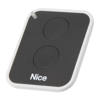
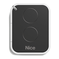
FM134
Two Button Entry Transmitter
If you already have a transmitter that operates
your gate and are simply adding an additional
transmitter, set the DIP switches in the new
transmitter to match the DIP switches in your
original transmitter, reassemble the transmitters
and you are done.
If you are replacing a lost transmitter and you know or have your original
transmitter’s DIP switch setting written down, set the new transmitter DIP
switches to that setting and it is ready to activate your gate opener.
If you don’t know the DIP switch setting from your original transmitter, you
will need to select a new setting.
Personalize your Transmitter Setting
There are nine (9) DIP switches, each of which can be placed in three
different positions (+,0,-). DO NOT set all switches in the same position,
such as all +, all -, or all zeros.
Program New Transmitter Setting to Gate Opener’s Memory
Some gate openers are programmed with a LEARN REMOTE or LEARN TRANSMITTER button and some
with the ON/OFF switch.
See page 4 for transmitter programming instructions for Mighty Mule MM271, MM272, MM371,
MM372, MM571 or MM572 Automatic Gate Openers.
NOTE: If the red light on the transmitter is dim or ickers when the transmitter button is pushed, the
transmitter battery may be weak. Replace when necessary with a A23S 12 Volt battery.
ORIGINAL
TRANSMITTER
NEW
TRANSMITTER
1 2 3 4 5 6 7 8 9
Instructions for adding additional entry transmitter(s)
Instructions for replacing a lost entry transmitter
1 2 3 4 5 6 7 8 9
1 2 3 4
ON
STATUS
LEARN RMT
LEARN
MAST LIMIT
S3
S2
OFF
SOFT START OFF
WARNING OFF
OPEN PULL
SLV OPEN DLY.
MODE1 OFF
MODE2 OFF
ON
ON
PUSH
SIMULT.
ON
ON
120 MIN MAX
AUTO CLOSE TIME STALL FORCE
+
or
IMPORTANT:
If you change the DIP switches in the
original transmitter refer to Program
New Transmitter Setting to Gate
Opener’s Memory section below.
Open transmitter to access
DIP switches
Reassemble the transmitter
when nished
FCC WARNING:
Changes or modications to this unit not expressly approved by the party responsible for compliance could void the user’s authority to operate the
equipment.
NOTICE: This device complies with part 15 of the FCC rules and with Industry Canada license-exempt RSS standard(s). Operation is subject to the following two
conditions: (1) this device may not cause interference, and (2) this device must accept any interference, including interference that may cause undesired operation of
the device.
Le présent appareil est conforme aux CNR d’Industrie Canada applicables aux appareils radio exempts de licence. L’exploitation est autorisée aux deux conditions
suivantes: (1) l’appareil ne doit pas produire de brouillage, et (2) l’utilisateur de l’appareil doit accepter tout brouillage radioélectrique subi, même si le brouillage est
susceptible d’en compromettre le fonctionnement.
However, there is no guarantee that interference will not occur in particular installations. If this equipment does cause harmful interference to radio or television
reception, which can be determined by turning the equipment off and on, the user is encouraged to try to correct the interference by one or more of the following
measures: • Reorient or replace the receiver antenna. • Increase the separation between the equipment and the receiver. • Connect the equipment into an outlet on a
circuit different from that to which the receiver is connected. • Consult the dealer or an experienced radio/TV technician for help.
You can have as many transmitters as you want for family and guests to open your gate. The DIP
switches in all the transmitters for a particular gate opener must be set the same.
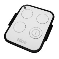
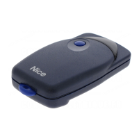
FM135
Single Button Entry Transmitter
2 3
 Loading...