Cod. 985719 – 00 / July 2004
18
5.2.3. Dismantling the plummer block with ball bearing and eccentric locking collar
1) Suspend the shaft between the bearing support bar and the impeller
2) unscrew the grub screw of the eccentric collar
3) Rotate the locking collar in the opposite direction to the direction of shaft rotation
4) Measure and mark the position of the bearing on the shaft
5) Unscrew the bolts of the plummer block
6) Remove with a file, the flash on the shaft produced by the grub screw
7) Remove the plummer block from the shaft with an extractor or tapping the inner ring of the bearing with a hammer
8) Replace the plummer block
5.2.4. Mounting the plummer block with ball bearing and eccentric locking collar
1) Carefully clean the shaft. If the shaft is not new, make sure that dimension and finishing are correct
2) Insert the bearing at the marked position on the shaft
3) Fully tighten the attachment bolts in the housing base
4) Place the eccentric locking collar on the inner ring extension and tighten it in the direction of rotation of the shaft
5) Tighten the grub screw without exceeding the maximum torque (see table in the paragraph above)
5.2.5. Dismantling the plummer block with ball bearing and adapter sleeve
1) Suspend the shaft between the bearing support bar and the impeller
2) Mark the position of the adapter sleeve on the shaft
3) Release the tap on the locking washer
4) Loosen the nut leaving it in position
5) Unscrew the attachment bolts of the housing base
6) Remove the plummer block from the shaft with an extractor or tapping the inner ring of the bearing with a hammer
7) Replace the plummer block
5.2.6. Mounting the plummer block with ball bearing and adapter sleeve
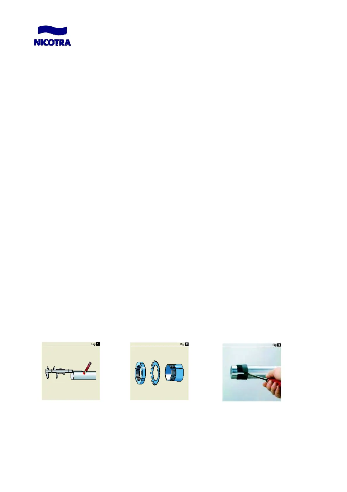
1) Carefully clean the shaft. If the shaft is not new, make sure that dimension and finishing are correct
2) Remove the nut and the locking washer from the adapter sleeve (fig.2)
3) Insert the sleeve at the marked position on the shaft (fig.1,3)
4) Slide the plummer block unit up on the adapter sleeve with the large end of the tapered bore leading
5) Insert the locking washer and screw the lock nut on to the adapter sleeve using the proper wrench according to the
tightening torque indicated in the table(fig.4)
6) Bend down a tap on the locking washer in one of the slots provided around the circumference of the nut (fig.5)
7) Align the two units and fully tighten the attachment bolts (fig.6)
 Loading...