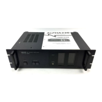
Do you have a question about the Nikko Alpha II and is the answer not in the manual?
Voltage specification for UL and CSA type amplifiers.
Voltage specification for Europe standard (universal) type.
Voltage specification for DEMKO and SEMKO type.
Voltage specification for DIN type amplifiers.
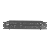
Control for powering the unit on/off and status indication.
Selects connected speaker systems (A, B, or A+B).
Adjusts meter sensitivity using four pushbutton steps.
Displays left/right channel output power levels in dB.
Connects preamplifier via pin-plug cord.
Connects speaker systems; color-coded for polarity.
Connects to the mains power supply.
Instruction to disconnect specific capacitors from the circuit.
Instruction to add a 5 pF capacitor between test points.
Instruction to add a 33 pF capacitor parallel to C711.
Detailed technical specifications for W, E, and N type units.
Detailed technical specifications for the D type unit.
Procedure for removing the top steel cover.
Steps for removing the meters.
Procedure for removing the bottom plate.
Steps for detaching the front panel.
Procedure for lamp replacement and board removal.
Procedure for removing meter switch circuit board.
Steps for regulator circuit board removal and service.
Procedure for protector circuit board removal and service.
Instructions for power transistor removal.
Detailed bottom view of the main amplifier circuit board.
List of packaging materials and accessories.
List of cabinet assembly parts.
List of chassis assembly components.
List of front plate assembly parts.
List of back plate assembly parts.
List of heatsink assembly components.
List of main amplifier board parts.
List of protector circuit board parts.
List of meter switch circuit board parts.
Required equipment for chassis alignment.
Procedure for midpoint voltage adjustment.
Procedure for idling current adjustment.
Procedure for meter sensitivity calibration.
Technical data for transistors.
Technical data for Field Effect Transistors.
Technical data for Zener Diodes.
Technical data for LEDs.