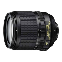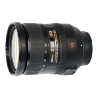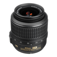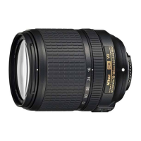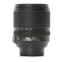
Do you have a question about the Nikon AF-S DX Zoom-Nikkor 18-105mm f/3.5-5.6G ED VR and is the answer not in the manual?
| Focal Length | 18-105mm |
|---|---|
| Maximum Aperture | f/3.5-5.6 |
| Lens Mount | Nikon F (DX) |
| Format Compatibility | APS-C / DX |
| Optical Design | 15 Elements in 11 Groups |
| Diaphragm Blades | 7, Rounded |
| Filter Size | 67 mm |
| Special Elements | 1 ED glass element, 1 Aspherical lens element |
| Image Stabilization | Yes (VR) |
| Minimum Focus Distance | 0.45m (1.48ft) |
| Dimensions | 76 x 89mm (3.0 x 3.5in) |
| Weight | 420g (14.8oz) |
| Angle of View | 76° - 15°20' |
| Autofocus | Yes (AF-S, Silent Wave Motor) |
Key safety, handling, and solder precautions before starting disassembly or reassembly.
Step-by-step guide for disassembling the main camera body components.
Instructions for removing the sheet and rubber ring from the zoom ring unit.
Procedure for detaching the rear cover ring by removing securing screws.
Steps to remove the 1st lens group unit and associated sheet.
Guidance on handling the 2nd lens group unit, including caution for its aspheric surface.
Instructions for removing the 5th lens group unit and its washer.
Steps to detach and remove the SW block unit from its connector.
Procedure for removing the bayonet mount unit and its lever, with a caution for the GND wire.
Instructions for removing the fixed tube unit.
Steps to remove the MF ring unit and its washer.
Guidance on disconnecting FPCs from the main PCB unit and removing the unit.
Instructions for detaching the GMR unit's FPC and removing the unit itself.
Procedure for removing the SWM unit, with a caution for the motor area.
Steps to remove the brush unit and the plate spring.
Instructions for removing the focus sliding ring and focus key.
Procedure for removing VCM-FPC and hall element PCB, and taking out screws.
Steps to remove the segment gear unit from the fixed ring unit 2.
Instructions for peeling tape and removing the zoom brush unit.
Procedure for removing the zoom ring unit by taking out a screw.
Steps for peeling tape and removing the relay-FPC unit from the fixed ring unit.
Instructions for removing silicone rubbers, zoom encoder FPC, and the zoom index ring.
Steps for removing the cover ring unit by taking out screws.
Instructions for removing the filter ring and roller unit.
Steps for assembling the filter ring and roller units for the 3-4G lens group unit 2.
Instructions for mounting and securing the cover ring.
Steps for adhering FPC, attaching the zoom index ring, and applying grease.
Instructions for adhering FPC, tape, and covering sheets for the relay-FPC unit.
Steps for mounting the zoom ring unit and applying grease to specific areas.
Procedure for applying grease and mounting the zoom brush unit.
Instructions for mounting and turning the segment gear ring unit.
Steps for setting units to WIDE-end and mounting the fixed ring unit 2.
Instructions for setting the zoom ring, aligning the focus sliding frame, and fitting it into grooves.
Steps for mounting the plate spring and the brush unit, with notes on insertion.
Procedure for mounting the SWM unit and tightening screws, with a caution for touching the motor area.
Instructions for mounting the GMR unit, attaching its FPC, and notes on inspection.
Steps for preliminary soldering, attaching tape, and mounting the main PCB unit.
Instructions for placing the MF ring unit with its reinforcing plate upward and applying grease.
Steps for mounting the fixed tube unit and applying grease to the rim.
Procedure for mounting washers, placing rollers, and routing GND lead wire.
Instructions for bending the SW block unit's FPC and connecting it to the connector.
Steps for setting zoom ring, mounting washer and 5th lens group, and inserting reference pins.
Guidance on handling the 2nd lens group unit, including caution for its aspheric surface.
Instructions for setting zoom ring to TELE-end, mounting washer and 1st lens group.
Steps for mounting the rear cover ring and tightening securing screws.
Instructions for adhering the sheet and mounting the zoom rubber ring.
Steps for peeling backing paper and adhering VR name plate and name plate.
Procedures for inspecting and adjusting GMR output waveform during assembly.
Steps to prepare the lens and connect measurement instruments for adjustment.
Guidance on inspecting and adjusting waveforms using oscilloscope and lens rotation.
Procedure for inspecting and adjusting the AF-contact pin position using a specialized tool.
Steps to adjust the aperture lever position for proper aperture blade operation.
Procedure for adjusting Focus-Face-Distance using collimator, software, and specific settings.
Setting up specialized equipment for lens optical alignment, including holders and charts.
Steps for preparing the camera and setting up the alignment chart for shooting.
Procedure to adjust field curvature by measuring focus positions and washer thickness.
Steps for mounting and adjusting the center positioning tool for the rear lens group holder.
Procedure for aligning the rear lens group using monitor, generator, and focus ring adjustments.
Instructions for preparing test charts and setting up the camera and lens for data writing.
Overview of adjustments for electrical devices and system requirements for the software.
Diagram and explanation of the system configuration for electrical adjustments.
Step-by-step guide for performing electrical device adjustments using the software.
Overview of inspections for lens operations, including GMR, driving, switches, and firmware.
Procedure for inspecting lens driving stop accuracy at various positions and focal lengths.
Steps to inspect lens driving time using an oscilloscope and by selecting drive amounts.
Procedure for inspecting lens switches and checking the operating condition of the focus encoder.
Steps to check the lens name and firmware version using the adjustment software.
Steps for setting up the VR lens adjustment equipment, including laser beam handling.
Instructions for starting the VR adjustment software and selecting the lens model.
Steps for attaching the adapter and moving the lens retainer stand to fix the lens.
Procedure for inspecting the VR mode switch position using the adjustment software.
Steps for adjusting VR lens position, including VCM polarity and angle confirmation.
Procedure for adjusting VR moving direction and gyro gain based on laser pointer movement.
Required tools and setup for writing aberration compensation data.
Instructions for preparing test charts and setting up the camera and lens for data writing.
Steps for writing aberration compensation data using the software, including focus area setting.
Details on specialized tools, software, and their part numbers.
List of greases, adhesives, and self-made tools used in the repair process.
