Chapter 3 Installation and Connection
7
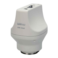
Specifications for External I/O Devices
To prepare an external I/O device, select the product satisfying the following specifications.
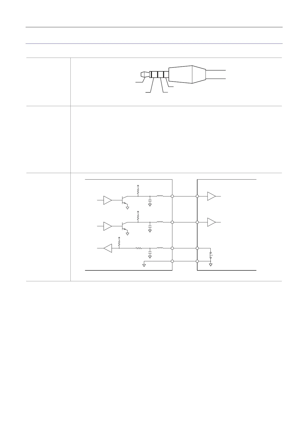
Connector
ø3.5, 4-pole pin mini-plug
Signal
Input
• Trigger-IN signal Input range 0 to 5 V
(TRG_IN) LOW level 0.8 V or less
HI level 2.4 V or over
Exposure starts at the rising edge
Output
• Exposure timing signal Output at the live operation or trigger operation
(EXP_TMG) HI: Currently in exposure process
• Trigger-ready signal HI: Trigger-ready status (ready to accept a trigger-IN signal)
(TRG_RDY) HI level 2.4 to 3.3 V
LOW level 0.0 to 0.8 V
Connection circuit
diagram
3.3V
470 PF
1 kΩ
6 kΩ
3.3V
470 PF
6 kΩ
3.3V
470 PF
100 kΩ
Note: For details, please contact your nearest Nikon representative.
4 pin: Exposure timing signal
(EXP_TMG)
1 pin: GND
3 pin: Trigger-IN signal
2 pin: Trigger-ready signal
(TRG_RDY)
DS-Ri2/DS-Qi2 side External device side
4 pin
2 pin
3 pin
GND
Switch
Exposure timing signal
(EXP_TMG)
Trigger-ready signal
(TRG_RDY)
Trigger-IN signal
(TRG_IN)