Do you have a question about the nilan Comfort 250 Top and is the answer not in the manual?
Essential safety warnings and cautions for unit operation and maintenance.
Information on electrical connection and grounding for the unit.
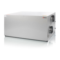
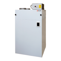
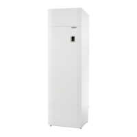
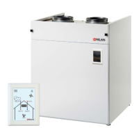
Overview of the ventilation unit and its purpose.
List of documents supplied with the unit and where to find more.
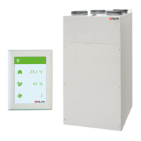
Details the Comfort 250 Top model and its features.
Labeled diagram identifying key parts of the ventilation unit.
For frost protection, enhances heat recovery efficiency during cold periods.
Controls supply air temperature, useful for dwelling heating.
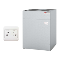
Utilizes hot water for supply air heating, with sensors and regulation.
Manages extract air for cooker hood extraction, includes filter.
Alternative to EM-box for managing extract air, suitable for limited space.
Connects external functions like user selections, Modbus, fire thermostat.
Enables control of fire dampers and external fire thermostats.
Reduces vibration transfer from the unit to the building structure.
Improves sound damping between the unit and duct system.
Enhances air quality by filtering pollen from outdoor air.
Provides extra filtration for extract air from cooker hoods.
Enables smartphone control of the ventilation unit via a gateway.
Guidelines for optimal unit placement considering service and drainage.
Specifies required space above the unit for flashing removal.
Instructions for using mounting brackets for wall installation.
Procedures for connecting duct pipes to the ventilation unit spouts.
Critical safety measures for electrical work on the unit.
Identifies 230V, external, and PC tool connection points on the unit.
Details the power supply connection via Schuko plug and grounding.
Overview of possible external accessory connections.
Table showing which accessories can be connected in different settings.
Details wiring for different connection boxes (Normal, Water, Electrical, Fire).
Explains usage of user selection inputs for cooker hoods and other applications.
Information on integrating the unit with external control systems via Modbus.
Connecting external indicators for unit alarms.
Connecting fire thermostats or automation systems to stop the unit.
Manages extract air for cooker hoods, cannot be used with fire automation.
Alternative to EM-box for cooker hood extract air management.
For frost protection, mounted in outdoor air duct.
For supply air temperature control, installed in supply air duct.
For supply air temperature control using hot water.
Details on connecting the condensate drain with a specific water trap.
Specifies measurements and type of water trap to be used.
Information on accessories for water after-heating elements.
Specific instructions for installing the water after-heating element in the duct.
Overview of the fire automation system's purpose and components.
Safety guidelines for working with the fire automation system.
Describes the system's monitoring, testing, and operational functions during a fire.
How to connect fire dampers using the Fire Connection Box.
Detailed wiring instructions for Belimo fire dampers.
Wiring configuration for connecting two fire dampers in series.
Explains alarm codes and the process for start-up and annual testing.
Procedures for manually testing fire and smoke damper positions.
How the fire thermostat interacts with the ventilation unit.
Describes release signals and operating signals affecting dampers and unit shutdown.
Template for documenting annual fire automatic system tests.
In-depth information on duct systems, legislation, and types.
Specifics on installing flexible NilAIR tubes for ventilation.
Recommends flexible connections for the ventilation unit.
Strategic placement of extract air valves in high-humidity rooms.
Strategic placement of supply air valves in living areas.
Positioning of roof terminals to prevent pressure oscillations and short-circuiting.
Visual example of a typical ventilation system installation.
Importance of correct system balancing for optimal operation and vacuum.