EasyManua.ls Logo

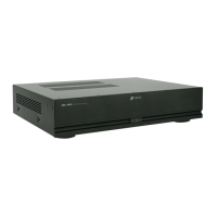
Niles IPC-6 User Manual

Niles IPC-6
10 pages
To Next Page IconTo Next Page
Page #1 background imageLoading...
Page #1 background image
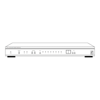
IPC-6
NILES
PROGRAM
POWER
IPC-6 INTELLIGE
NT POWER CONTROLLER
A-TRIGGER-B
ON OFF
123456C1C2
SELECT TIME
INSTALLATION & OPERATION GUIDE
NILES
®
MODEL
IPC-6
INTELLIGENT POWER CONTROLLER
IPC-6
Niles Audio
Corporation
www.nilesaudio.com
12331 S.W. 130 Street
Miami, Florida 33186
Tel: (305) 238-4373
Fax: (305) 238-0185
NILES
®
©1999 Niles Audio Corporation. All rights reserved. Niles and the Niles logo are registered trademarks
of Niles Audio Corporation. All other trademarks are the properties of their respective owners. Because
we continually strive to improve our products, Niles reserves the right to change product specifications
without notice. The technical and other information contained herein is not intended to set forth all
technical and other specifications of Niles products. Additional information can be obtained on-line at
www.nilesaudio.com or by calling Niles at 1-800-289-4434. Printed in USA 5/99 LT00089D.
Other manuals for Niles IPC-6

Questions and Answers:

Niles IPC-6 Specifications

General IconGeneral
BrandNiles
ModelIPC-6
CategoryController
LanguageEnglish

Summary

Introduction

TOOLS REQUIRED

Features and Benefits

Installation Considerations

IPC-6 Total Power Capacity

Specifies the maximum wattage limit for devices connected to the IPC-6 and alternative solutions.

IPC-6 Low Voltage Contacts (C1 & C2 Controlled Outputs)

Explains the function of low voltage contacts for controlling external devices.

12 Volt Trigger Inputs

Describes the acceptable voltage range for external trigger signals to control the IPC-6.

Switched 120 Volt AC Outlets

Guides users on how to test components for "latching" power control compatibility.

Installation

Programming

Measuring Power "On" and "Standby" States

Details how to use the Accusense™ circuitry to measure device power states for accurate triggering.

Programming Switched 120 volt and Controlled (low voltage) Outlets

Explains how to program trigger sources, turn-on, and turn-off time delays for outlets and control outputs.

Enter the PS programming mode

Instructs users on how to access the specific programming mode for setting up sequences and delays.

Errors - The display reads E1

Describes how to interpret and resolve the 'E1' error code, usually related to incorrect trigger device connections.

Cancel Programming

Provides instructions on how to exit the programming mode at any stage without saving changes.

Troubleshooting

SPECIFICATIONS

Related product manuals