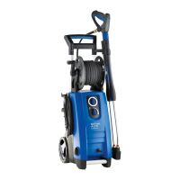
Do you have a question about the Nilfisk-ALTO POSEIDON 2-29 and is the answer not in the manual?
Exploded view diagram detailing the cabinet components of the POSEIDON 2.
Diagram of the motor/pump unit with assembly torque and glue specifications.
Step-by-step guide for removing and installing the front cabinet of the machine.
Procedure for taking apart and reassembling the switchbox and motor cover.
Detailed steps for disassembling and assembling the pump unit.
Instructions for removing the brass connector located inside the outlet.
Procedure for disassembling and assembling the start and stop valve mechanism.
Guide for adjusting valve settings to achieve specified standby pressure.
Procedure for correctly adjusting the micro switch for optimal functionality.
Instructions for changing the hose on the hose reel version of the machine.
Guidance on measuring electrical motor resistance for different motor types.
Information on recommended and alternative oil types for the machine.
Details on recommended lubricants for seals and O-rings.
List of recommended adhesives and their applications.
Listing of essential tools required for maintenance and repair.
Diagram illustrating the machine's state when stopped and outlet hose is empty.
Diagram showing the machine's hydraulic system during normal operation.
Diagram illustrating the machine's hydraulic system when in standby mode.
Schematic showing the electrical wiring connections of the machine.
Schematic illustrating the functional circuit of the machine's electrical system.
| Hose Length | 5 m |
|---|---|
| Voltage | 230 V |
| Frequency | 50 Hz |
| Protection Class | IPX5 |
| Inlet/Outlet Connection | 3/4 inch |
