WARNING: The cylinder valve can fly off with
enough force to kill if the valve unscrews from the cylin-
der. LOOK at valve when removing cylinder. STOP if the
valve starts to unscrew from the cylinder. Screw it back
on and contact the manufacturer for instructions to
repair.
WARNING: THE LPRV2 RESETTING PRES-
SURE RELIEF #1-4 IS NOT USER SERVICABLE. DO NOT
REMOVE OR TAMPER WITH THE LPRV2 PRESSURE
RELIEF.
WARNING: NEVER OPERATE OR ADJUST THE
LPRV2 WITH THE MAINTENANCE SET SCREW #12
LOOSE OR REMOVED. NEVER ATTACH AN AIR SOURCE
WITH THE LPRV2 CAP #13 NOT FULLY INSTALLED WITH
THE MAINTENANCE SCREW #12 FIRMLY INSTALLED. IF
THE LPRV2 CAP IS LOOSE OR REMOVED THE LPRV2
PISTON IS UNDER PRESSURE AND CAN TRAVEL AT
VELOCITIES, WHICH MAY CAUSE PERSONAL INJURY
TO THE USER OR BYSTANDERS.
WARNING: THIS IS NOT A TOY IMPROPER
USE CAN RESULT IN INJURY OR DEATH DO NOT USE
THE LPRV2 PRIOR TO READING THIS MANUAL IN ITS
ENTIRET.
NOTE: COMPONENT COLOR FOR ILLUSTRATION PURPOSES ONLY
ACTUAL PRODUCT COLOR MAY VARY.
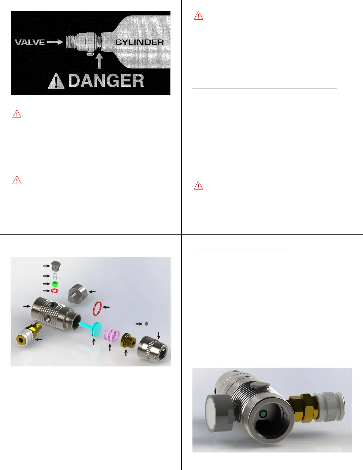
PARTS DIAGRAM:
1. LPRV2 Pressure Relief Housing
2. LPRV2 Pressure Relief Spring
3. LPRV2 Pressure Relief Piston
4. LPRV2 Pressure Relief Piston 009-70 Buna O-ring
5. LPRV2 Low Pressure Gauge
6. LPRV2 Body
7. LPRV2 Piston 015 – 90 Red Urethane O-ring
8. Low Pressure Fosters Quick Disconnect
9. LPRV2 Piston
10. LPRV2 Main Spring
11. LPRV2 Adjuster
12. LPRV2 Maintenance Access Locking set screw
13. LPRV2 Cap
1
2
3
4
12
10
11
13
9
6
5
7
8
MAINTENANCE AND SERVICE (reference figure 2):
Maintaining the Ninja LPRV2 for optimum performance
requires occasional Piston O-ring #7 replacement.
Replacing and silicone greasing oring #7 will solve a number
of common air pressure regulation issues:
1. Inconsistent pressure output.
2. Slow loss of pressure while under pressure but not using
the regulated air.
3. Slow recharging of set pressure.
4. Leaking from LPRV2 cap #13, LPRV2 adjuster #11, LPRV2
Maintenance set screw #12.
Figure 2
Figure 3
DISASSEMBLY (reference figure 2):
1. Remove Air Source.
2. Using a 3/16” Allen (hex) key rotate the LPRV2 Adjuster
#11 fully Counter Clockwise.
3. Using a 5/64” Allen (hex) key remove the LPRV2 Mainte-
nance Access Locking set screw #12 by rotating Counter
Clockwise using a flat, non-ball end of the Allen.
4. Rotate LPRV2 cap #13 Counter Clockwise to remove
LPRV2 cap and Adjuster.
5. Remove LPRV2 Main Spring #10
6. Remove LPRV2 Piston #9 by light pressing an Allen key
through the center hole on the Air Source Attachment side
(Figure 3: X)
7. Remove and replace oring #7, lightly lube the O-ring with
silicone grease.
© 2010-2023 Pressure Specialist Inc. © 2010-2023 Pressure Specialist Inc.
© 2010-2023 Pressure Specialist Inc. © 2010-2023 Pressure Specialist Inc.
 Loading...