EasyManua.ls Logo

Nippon DENON DR-M12HX User Manual

Nippon DENON DR-M12HX
44 pages
To Next Page IconTo Next Page
Page #1 background imageLoading...
Page #1 background image
DENON.
„=.
SERVICE
MANUAL
STEREO
CASSETTE
TAPE
DECK
MODEL
DR-M12HX/M14HX
DR-M14HX
NIPPON
COLUMBIA
CO.
LTD.
Question and Answer IconNeed help?

Do you have a question about the Nippon DENON DR-M12HX and is the answer not in the manual?

Nippon DENON DR-M12HX Specifications

General IconGeneral
TypeCassette Deck
Track System4-track, 2-channel stereo
Tape Speed4.8 cm/s
Heads1 x Record/Playback, 1 x Erase
Tape TypeType I, CrO2, Metal
Frequency Response20Hz to 19kHz (Metal tape)
Signal to Noise Ratio75dB (Dolby C)
Weight5.5 kg
Noise ReductionB, C
InputsLine In
OutputsLine Out
Wow and Flutter0.04% WRMS

Summary

FEATURES

SPECIFICATIONS

WARNINGS AND SAFETY PRECAUTIONS

Component Parts Safety

Identifies safety-critical component parts for replacement.

Leakage Current Safety Testing

Outlines procedure for testing appliance leakage current.

BLOCK DIAGRAM

LEVEL DIAGRAM

Playback System Level Diagram

Illustrates signal levels during playback operation.

Recording System Level Diagram

Illustrates signal levels during recording operation.

PART NAMES AND FUNCTIONS

Front Panel Controls Overview

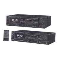
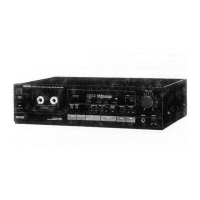
Identifies and describes front panel controls and indicators.

Bias and Output Level Controls

Explains bias adjustment and output level control functions.

DISASSEMBLY INSTRUCTIONS

Front Panel and Mechanism Removal

Step-by-step guide for removing front panel and mechanisms.

Meter Window and Input Board Removal

Procedures for removing meter window and input volume board.

MECHANISM SECTION ADJUSTMENTS

Pinch Roller and Head Replacement

Procedures for replacing pinch roller and playback/erase heads.

R/P Head Adjustment Procedure

Details azimuth adjustment for the record/playback head.

ELECTRICAL SECTIONS ADJUSTMENTS

Required Instruments and Caution

Lists necessary instruments and pre-adjustment cautions.

Tape Transport and Azimuth Adjustment

Covers tape transport checks and R/P head azimuth alignment.

Tape Speed and Playback Adjustments

Details procedures for checking tape speed and adjusting playback.

Recording Section Adjustments

Outlines adjustments for recording frequency response and levels.

AUDIO UNIT PARTS LIST

Semiconductor and Resistor Components

Lists semiconductor and resistor parts for the audio unit.

Capacitor Components

Lists capacitor parts for the audio unit.

Other Parts and Accessories

Details other parts and packing/accessories for the audio unit.

PARTS LIST OF EXPLODED VIEW

Exploded View Components List

Lists parts shown in exploded diagrams.

Packing and Accessories List

Lists packing materials and accessories.

EXPLODED VIEW OF CABINET AND CHASSIS

PARTS LIST OF VM151 MECHANISM UNIT

Mechanism Unit Semiconductor and Resistors

Lists semiconductor and resistor parts for the mechanism unit.

Mechanism Unit Capacitors and Other Parts

Lists capacitor and other parts for the mechanism unit.

POWER SUPPLY UNIT PARTS LIST

Power Supply Semiconductor and Resistors

Lists semiconductor and resistor parts for the power supply unit.

Power Supply Capacitors and Other Parts

Lists capacitor and other parts for the power supply unit.

EXPLODED VIEW OF VM151 MECHANISM UNIT

2U-1436-1 AUDIO PWB SCHEMATIC

WIRING DIAGRAM (DR-M12HX)

WIRING DIAGRAM (DR-M14HX)

SCHEMATIC DIAGRAM OF AUDIO UNIT (DR-M12HX)

SCHEMATIC DIAGRAM OF POWER UNIT (DR-M12HX)

SCHEMATIC DIAGRAM OF AUDIO UNIT (DR-M14HX)

SCHEMATIC DIAGRAM OF POWER UNIT (DR-M14HX)

P. W. BOARD 2U-1437 POWER SUPPLY UNIT

P. W. BOARD OF 2U-1437 AND 2U-1438 UNIT

2U-1437 Power Supply PWB Layout

Shows the printed wiring board layout for the power supply unit.

2U-1438 Mechanism PWB Layout

Shows the printed wiring board layout for the mechanism unit.

SEMICONDUCTOR COMPONENTS

Integrated Circuits and Diodes

Details integrated circuits and diodes used in the unit.

Transistors

Related product manuals