EasyManua.ls Logo

Nippon DENON DR-M20 User Manual

Nippon DENON DR-M20
30 pages
To Next Page IconTo Next Page
Page #1 background imageLoading...
Page #1 background image
Hi-Fi
Component
CK
STEREO
CASSETTE
TAPE
DE
Question and Answer IconNeed help?

Do you have a question about the Nippon DENON DR-M20 and is the answer not in the manual?

Nippon DENON DR-M20 Specifications

General IconGeneral
BrandNippon
ModelDENON DR-M20
CategoryTape Deck
LanguageEnglish

Summary

SPECIFICATIONS

WARNING

Component parts

Safety warning about component parts and shading.

Leakage current

Test leakage current before returning unit, must not exceed 0.5mA.

BLOCK DIAGRAM

LEVEL DIAGRAM

PLAYBACK SYSTEM

Diagrams and levels for the playback system of the cassette deck.

RECORDING SYSTEM

Diagrams and levels for the recording system of the cassette deck.

PART NAMES AND FUNCTIONS

Outline of the Mechanism Control Microcomputer

DISASSEMBLY INSTRUCTIONS

How to Remove the Front Panel

Step-by-step instructions for removing the front panel assembly.

How to Remove the Mechanisms

Instructions for removing the main cassette mechanism unit.

How to Remove the Meter Window and the Color Filter

Steps to remove the meter window and color filter.

How to removed the Meter Holder and the Counter/Meter Circuit Board, the LED circuit Board

Guide to removing meter holder, counter/meter circuit board, and LED circuit board.

DISASSEMBLY INSTRUCTIONS

How to Remove the Front Esc Ass'y

Instructions for removing the front esc (escutcheon) assembly.

How to Remove the Volume Circuit Board

Steps to remove the volume control circuit board.

How to Remove the Control Circuit Board

Procedure for removing the control circuit board.

How to Remove the Audio Circuit Board

Steps for removing the audio amplifier circuit board.

DISASSEMBLY INSTRUCTIONS

How to Remove the Logic Circuit Board

Instructions for removing the logic circuit board.

How to Remove the Power Switch Circuit Board

Steps to remove the power switch circuit board.

ADJUSTING AND CHECKING THE MECHANISM SECTION

Replacing the Pinch Roller

Procedure for replacing the pinch roller and checking tape transport.

Checking the Pressure Force of the Pinch Roller

How to check and verify the pinch roller pressure force.

Replacing the Record/Playback Head

Instructions for removing and replacing the record/playback (R/P) head.

Adjusting the R/P HEAD

Steps for adjusting the height and alignment of the R/P head.

ADJUSTING AND CHECKING THE MECHANISM SECTION

Adjustment and Replacement of Erasing Head

Steps for adjusting the height and tilt angle, and replacing the erasing head.

Height Adjustment of the Tape Guide

Procedure for adjusting the height of the tape guide using a jig.

Checking the Take-up Torque

How to check the take-up torque and related motor voltage.

ADJUSTING THE ELECTRICAL SECTIONS

Tape Transport Check

Check tape transport operation and tape guide alignment with a lamp.

ADJUSTING THE ELECTRICAL SECTIONS

Adjusting the Azimuth

Procedure to adjust azimuth alignment using a test tape.

Checking and Adjusting the Tape Speed

How to check and adjust the tape speed using a frequency counter.

Adjusting the Input Sensitivity

Steps to set the input signal level for proper sensitivity.

Adjusting Playback Section

Adjusting playback level and frequency response.

ADJUSTING THE ELECTRICAL SECTIONS

Adjusting the FL Meter

Procedure to adjust the FL meter indication based on output level.

Adjusting the Recording Section

Adjusting the record/playback frequency response and levels.

KU-5880 AUDIO PWB UNIT

KU-5870 POWER LOGIC UNIT

PARTS LIST OF EXPLODED VIEW

EXPLODED VIEW OF CABINET AND CHASSIS GROUP

EXPLODED VIEW OF MECHANISM VM860 UNIT

PARTS LIST OF CASSETTE MECHANISM EXPLODED VIEW

KU-5860 MECHANISM P.W.B UNIT

Parts list for the KU-5860 mechanism PWB unit.

ACCESSORIES GROUP

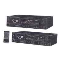
List of accessories included with the unit.

CARTON CASE GROUP

Parts list for carton case components.

WARNING

Parts Handling Warning

Warning about parts marked with shading for safety, use specified replacements.

SCHEMATIC DIAGRAM OF AUDIO AMP UNIT

P.W. BOARD OF KU-5880 AUDIO AMP UNIT

SCHEMATIC DIAGRAM OF POWER/LOGIC UNIT

P.W. BOARD OF KU-5870 POWER/LOGIC UNIT AND KU-5890 MECHANISM UNIT

SCHEMATIC DIAGRAM OF COUNTER METER UNIT

SEMICONDUCTORS

WIRING DIAGRAM

Related product manuals