ENGINE UNIT
EM-109
< UNIT DISASSEMBLY AND ASSEMBLY >
[VQ40DE]
C
D
E
F
G
H
I
J
K
L
M
A
EM
N
P
O
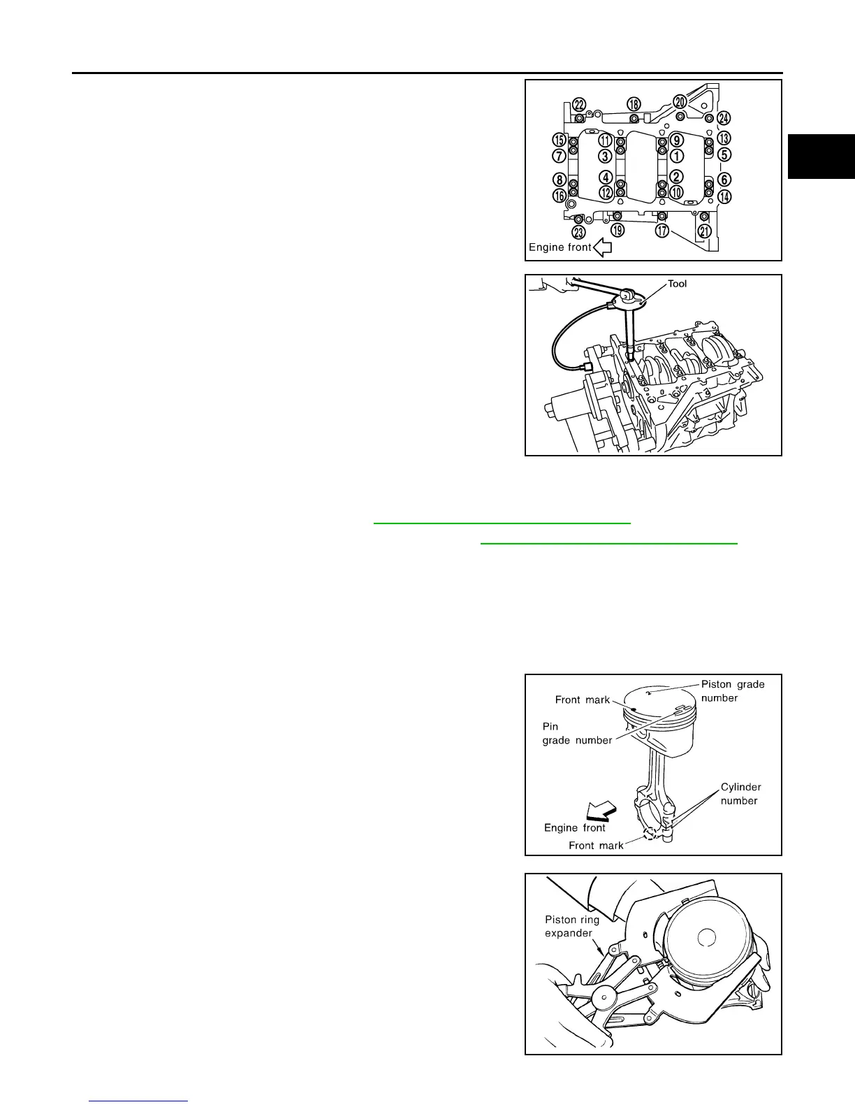
i. Tighten M10 bolts in numerical order as shown from No. 1 to 16.
NOTE:
Use socket (size E14) for bolts No. 1 to 16 (M10 bolt).
ii. Turn M10 bolts 90° clockwise in numerical order from No. 1 to
16 using Tool.
CAUTION:
Use angle wrench Tool to check tightening angle. Do not
make judgement by visual inspection.
• After installing the bolts, make sure that crankshaft can be rotated smoothly by hand.
• Wipe off completely any protruding liquid gasket on front side of the engine.
• Check the crankshaft end play. Refer to EM-112, "Inspection After Disassembly"
.
8. Inspect the outer diameter of connecting rod bolt. Refer to EM-112, "Inspection After Disassembly"
.
9. Install piston to connecting rod as follows:
a. Install new snap ring to the groove of piston rear side using suitable tool.
• Insert it fully into groove to install.
b. Install piston to connecting rod.
• Using industrial use drier or similar tool, heat piston until piston pin can be pushed in by hand without
excess force [approximately 60° to 70 °C (140° to 158 °F)]. From the front to the rear, insert piston pin
into piston and connecting rod.
• Assemble so that the front mark on the piston head and the
cylinder number on connecting rod are positioned as shown.
c. Install new snap ring to the groove of the piston front side.
• Insert it fully into groove to install.
• After installing, make sure that connecting rod moves
smoothly.
10. Install piston rings using piston ring expander or suitable tool.
CAUTION:
• When installing piston rings, be careful not to damage
piston.
• Be careful not to damage piston rings by expending them
excessively.
Bolts 1 - 16 : 35.3 N·m (3.6 kg-m, 26 ft-lb)
PBIC2941E
Tool number : KV10112100 (BT-8653-A)
WBIA0584E
SEM838F
PBIC0087E
Revision: January 2013 2013 Xterra