EM-110
< UNIT DISASSEMBLY AND ASSEMBLY >
[VQ40DE]
ENGINE UNIT
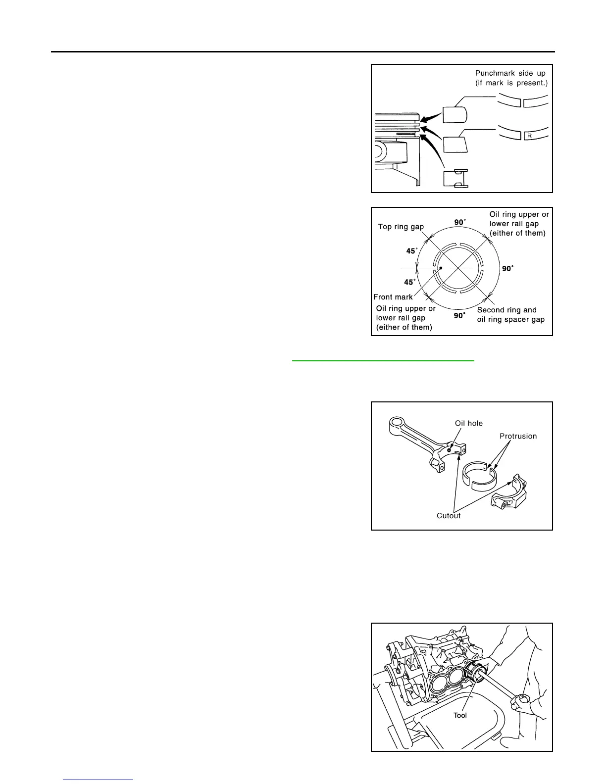
• If there is stamped mark on ring, mount it with marked side up.
NOTE:
If there is no stamp on ring, no specific orientation is required
for installation.
• Position each ring with the gap as shown referring to the pis-
ton front mark.
• Check the piston ring side clearance. Refer to EM-112, "Inspection After Disassembly"
.
11. Install connecting rod bearings to connecting rod and connecting rod bearing cap.
• Before installing connecting rod bearings, apply engine oil to the bearing surface (inside). Do not apply
engine oil to the back surface, but thoroughly clean it.
• When installing, align connecting rod bearing stopper protru-
sion with cutout of connecting rods and connecting rod bearing
caps to install.
• Ensure the oil hole on connecting rod and that on the corre-
sponding bearing are aligned.
12. Install piston and connecting rod assembly to crankshaft.
13. Position crankshaft pin corresponding to connecting rod to be installed onto the bottom dead center.
14. Apply engine oil sufficiently to the cylinder bore, piston and crankshaft pin journal.
15. Match the cylinder position with the cylinder number on connecting rod to install.
NOTE:
Be sure that front mark on piston head is facing front of engine.
16. Install piston with the front mark on the piston head facing the
front of engine using Tool.
CAUTION:
Be careful not to damage the cylinder wall and crankshaft
pin, resulting from an interference of the connecting rod big
end.
Stamped mark:
Top ring : —
Second ring : R
SEM757G
PBIC0808E
PBIC2067E
Tool number : EM03470000 (J-8037)
WBIA0585E
Revision: January 2013 2013 Xterra