ENGINE UNIT
EM-111
< UNIT DISASSEMBLY AND ASSEMBLY >
[VQ40DE]
C
D
E
F
G
H
I
J
K
L
M
A
EM
N
P
O
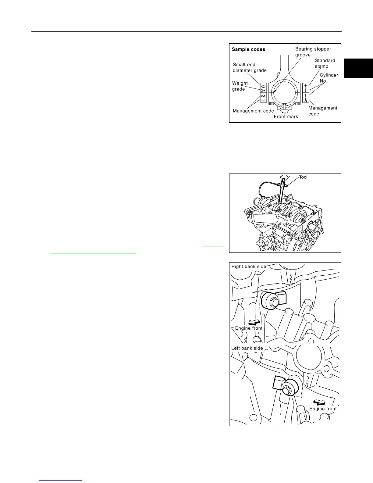
17. Install connecting rod bearing cap.
• Match the stamped cylinder number marks on connecting rod
with those on connecting rod bearing cap to install.
• Be sure that front mark on connecting rod bearing cap is fac-
ing front of engine.
18. Tighten connecting rod bolts in two steps as follows:
a. Apply engine oil to the threads and seats of connecting rod bolts. Tighten the connecting rod bolts to spec-
ification
b. Then tighten (turning clockwise) all connecting rod bolts 90°
using Tool.
CAUTION:
Always use Tool. Avoid tightening based on visual check
alone.
• After tightening connecting rod bolts, make sure that crank-
shaft rotates smoothly.
• Check the connecting rod side clearance. Refer to EM-112,
"Inspection After Disassembly".
19. Install knock sensors.
• Install knock sensor so that harness connector faces rear of
engine.
• After installing knock sensor, connect harness connector, and
lay it out to rear of engine.
CAUTION:
• Do not tighten bolts while holding harness connector.
• If knock sensor is dropped, replace it with new one.
NOTE:
• Make sure that there is no foreign material on the cylinder
block mating surface and the back surface of knock sensor.
• Make sure that knock sensor does not interfere with other
parts.
20. Assembly is in the reverse order of disassembly after this step.
Flywheel (M/T models)
• Install flywheel.
PBIC0809E
Connecting rod bolt : 19.6 N·m (2.0 kg-m, 14 ft-lb)
Tool number : KV10112100 (BT-8653-A)
WBIA0586E
Knock sensor bolts : 18.1 N·m (1.8 kg-m, 13 ft-lb)
PBIC2948E
Revision: January 2013 2013 Xterra