EM-122
< UNIT DISASSEMBLY AND ASSEMBLY >
[VQ40DE]
ENGINE UNIT
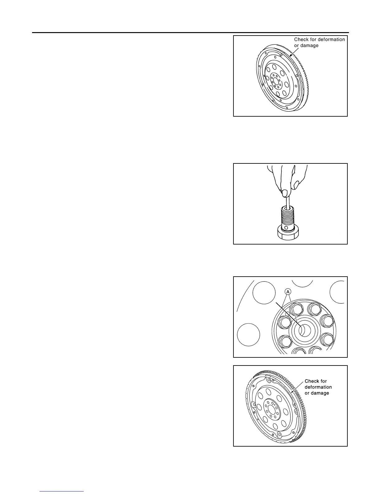
• Check drive plate and signal plate for deformation or cracks.
CAUTION:
• Do not disassemble drive plate.
• Do not place drive plate with signal plate facing down.
• When handling signal plate, take care not to damage or
scratch it.
• Handle signal plate in a manner that prevents it from becom-
ing magnetized.
• If anything is found, replace drive plate.
OIL JET
• Check nozzle for deformation and damage.
• Blow compressed air from nozzle, and check for clogs.
• If it is not satisfied, clean or replace oil jet.
OIL JET RELIEF VALVE
• Using clean plastic stick, press check valve in oil jet relief valve.
Make sure that valve moves smoothly with proper reaction force.
• If it is not satisfied, replace oil jet relief valve.
Dowel Pin Alignment INFOID:0000000008799006
REMOVAL
1. Use suitable tool to lock the drive plate (A/T models) or flywheel
(M/T models) and match mark (A) the drive plate or flywheel
before removing the bolts.
CAUTION:
Do not damage the ring gear teeth, or the signal plate teeth
behind the ring gear.
2. Remove drive plate (A/T models) or flywheel (M/T models).
• Loosen the drive plate or flywheel bolts in a diagonal order.
CAUTION:
• Do not place drive plate (A/T models) or flywheel (M/T
models) with signal plate facing down.
• When handling the signal plate, take care not to damage
or scratch it.
• Handle the signal plate in a manner that prevents it from
becoming magnetized
INSTALLATION (A/T MODELS)
1. Installation is in the reverse order of removal.
PBIC2938E
EMU0468D
ALBIA0522ZZ
SEM760G
Revision: January 2013 2013 Xterra