ENGINE UNIT
EM-123
< UNIT DISASSEMBLY AND ASSEMBLY >
[VQ40DE]
C
D
E
F
G
H
I
J
K
L
M
A
EM
N
P
O
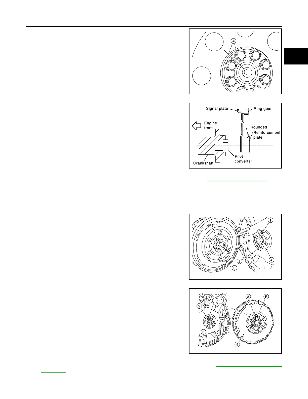
• When installing the drive plate to the crankshaft, use the
match mark (A) as shown to correctly align the crankshaft side
dowel pin to the drive plate side dowel pin hole.
• Install the drive plate and the reinforcement plate in the direc-
tion as shown.
• Tighten the drive plate bolts in a diagonal pattern in two steps. Refer to EM-102, "Exploded View"
.
INSTALLATION (M/T MODELS)
1. Installation is in the reverse order of removal after the following.
• Be sure the dowel pin is installed in the crankshaft.
• When installing the flywheel (3) to the crankshaft (2), be sure
to correctly align crankshaft side dowel pin (1) to the flywheel
side dowel pin hole (A) as shown.
- Oil seal (4)
• There is a locator mark (B) on the clutch cover side of the fly-
wheel (4). Refer to this for ease of installation.
- Crankshaft dowel pin (1)
- Oil seal (2)
- Crankshaft (3)
- Flywheel (4)
- Dowel pin hole (A)
- Dowel pin locator mark (B)
• Tighten the flywheel bolts in a diagonal pattern in two steps. Refer to EM-103, "Disassembly and
Assembly".
ALBIA0522ZZ
PBIC0910E
AWBIA0539ZZ
AWBIA0540ZZ
Revision: January 2013 2013 Xterra