EM-18
< PERIODIC MAINTENANCE >
[VQ40DE]
CAMSHAFT VALVE CLEARANCE
CAMSHAFT VALVE CLEARANCE
Valve Clearance INFOID:0000000008798960
INSPECTION
NOTE:
Perform the following inspection after removal, installation or replacement of camshaft or valve-related parts,
or if there are unusual engine conditions due to changes in valve clearance over time (starting, idling, and/or
noise).
1. Remove the air cleaner and air duct assembly. Refer to EM-24, "Exploded View"
.
2. Remove rocker covers (RH and LH banks). Refer to EM-41, "Removal and Installation"
.
3. Measure the valve clearance as follows:
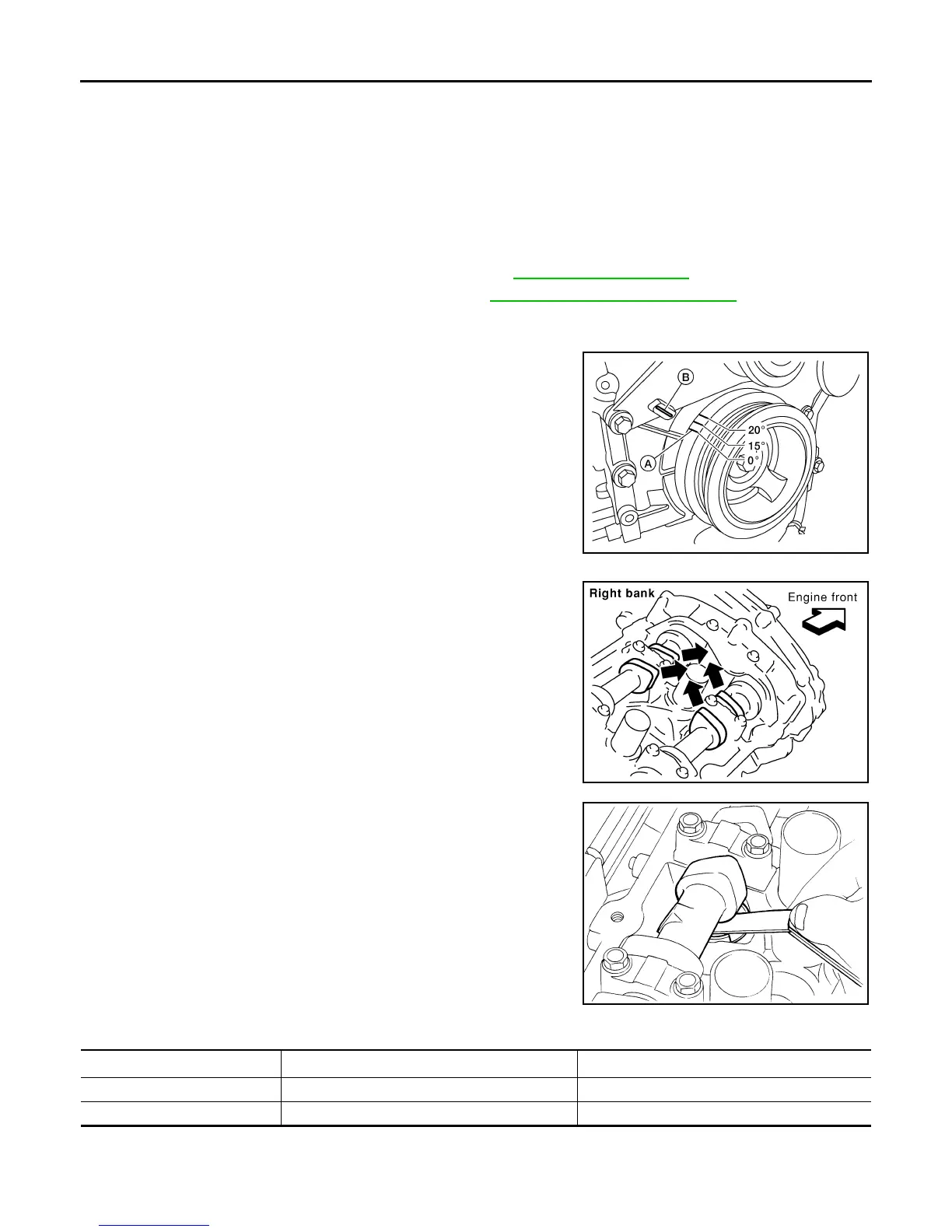
a. Set No. 1 cylinder at TDC of its compression stroke.
• Rotate crankshaft pulley clockwise to align timing mark (A)
(grooved line without color) with timing indicator (B).
• Make sure that intake and exhaust cam noses on No. 1 cylin-
der (engine front side of RH bank) are located as shown.
• If not, rotate crankshaft one revolution (360°) and align as
shown.
b. Use feeler gauge to measure the clearance between valve lifter
and camshaft.
Unit: mm (in)
1
: Approximately 20°C (68°F)
2
: Approximately 80°C (176°F)
AWBIA0719ZZ
SEM418G
SEM139D
Valve Clearance
Cold
1
(reference data) Hot
2
(reference data)
Intake 0.26 - 0.34 (0.010 - 0.013) 0.304 - 0.416 (0.012 - 0.016)
Exhaust 0.29 - 0.37 (0.011 - 0.015) 0.308 - 0.432 (0.012 - 0.017)
Revision: January 2013 2013 Xterra