CAMSHAFT VALVE CLEARANCE
EM-19
< PERIODIC MAINTENANCE >
[VQ40DE]
C
D
E
F
G
H
I
J
K
L
M
A
EM
N
P
O
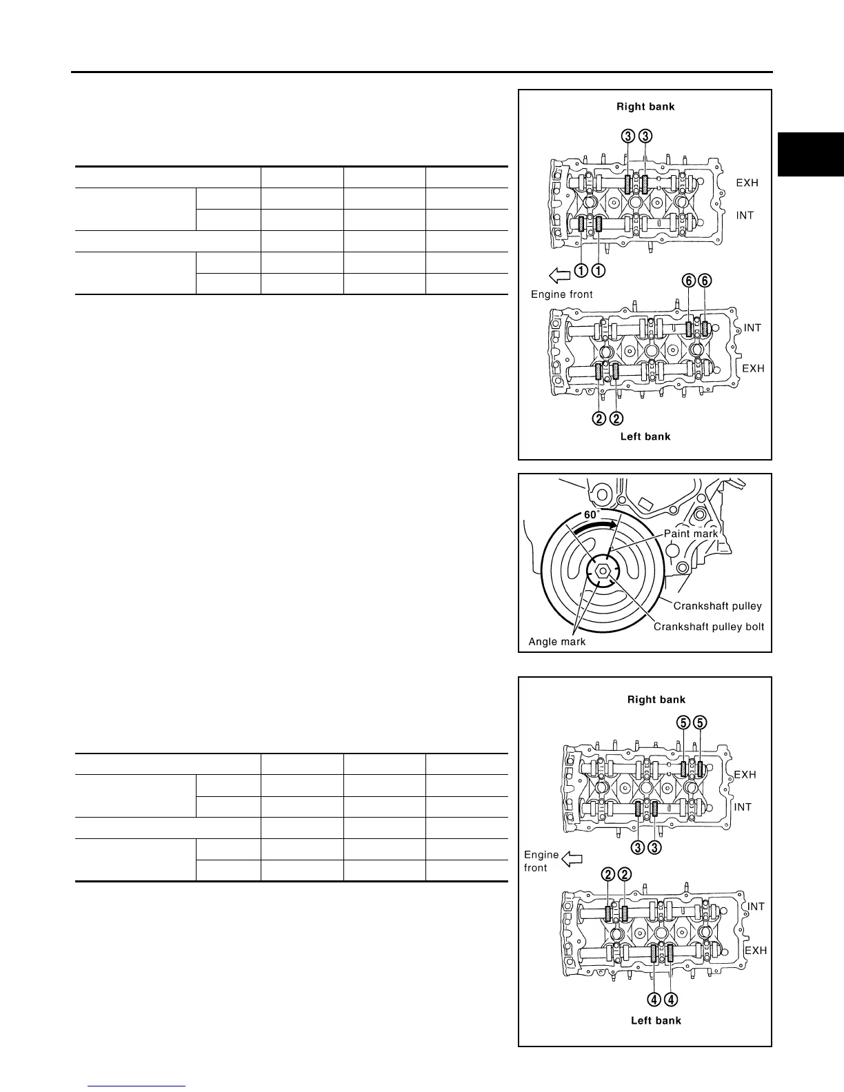
• Measure the valve clearances at locations marked “×” as
shown in the table below (locations indicated in the illustration)
with feeler gauge.
• No. 1 cylinder at compression TDC
c. Rotate crankshaft by 240° clockwise (when viewed from engine
front) to align No. 3 cylinder at TDC of its compression stroke.
NOTE:
Crankshaft pulley bolt flange has a stamped line every 60°. They
can be used as a guide to rotation angle.
• Measure the valve clearances at locations marked “×” as
shown in the table below (locations indicated in the illustration)
with feeler gauge.
• No. 3 cylinder at compression TDC
Measuring position (RH bank) No. 1 CYL. No. 3 CYL. No. 5 CYL.
No. 1 cylinder at
compression TDC
EXH ×
INT ×
Measuring position (LH bank) No. 2 CYL. No. 4 CYL. No. 6 CYL.
No. 1 cylinder at
compression TDC
INT ×
EXH ×
PBIC2054E
PBIC2916E
Measuring position (RH bank) No. 1 CYL. No. 3 CYL. No. 5 CYL.
No. 3 cylinder at
compression TDC
EXH ×
INT ×
Measuring position (LH bank) No. 2 CYL. No. 4 CYL. No. 6 CYL.
No. 3 cylinder at
compression TDC
INT ×
EXH ×
PBIC2055E
Revision: January 2013 2013 Xterra