EM-52
< REMOVAL AND INSTALLATION >
[VQ40DE]
FRONT TIMING CHAIN CASE
7. Remove power steering oil pump from bracket with piping connected, and temporarily secure it aside.
Refer to ST-17, "Removal and Installation"
.
8. Remove power steering oil pump bracket. Refer to ST-17, "Removal and Installation"
.
9. Remove generator. Refer to CHG-27, "Removal and Installation"
.
10. Remove water bypass hoses and water hose clamp.
11. Remove engine cooling fan (Crankshaft driven type) and fan bracket. Refer to CO-18, "Removal and
Installation (Crankshaft driven type)".
12. Remove water hose at oil cooler.
13. Remove oil cooler water bypass pipe from front timing chain case. Refer to EM-51, "Exploded View"
.
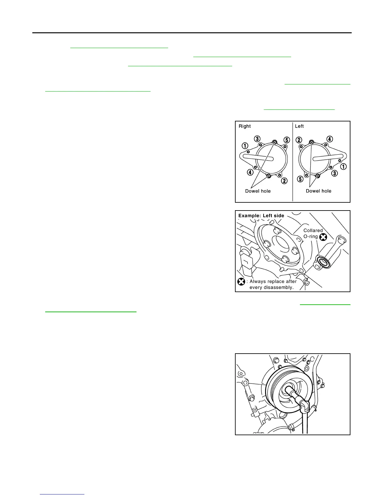
14. Remove right and left intake valve timing control covers.
• Loosen bolts in reverse order as shown.
• Cut liquid gasket for removal using Tool.
CAUTION:
• Shaft is internally jointed with camshaft sprocket (INT)
center hole. When removing, keep it horizontal until it is
completely disconnected.
• Do not damage the mating surfaces.
15. Remove collared O-rings from front timing chain case (left and
right side).
CAUTION:
Do not reuse O-rings.
16. Remove A/C compressor bolts and temporarily secure A/C compressor aside. Refer to HA-28, "Removal
and Installation of Compressor".
17. Remove crankshaft pulley as follows:
a. Remove access plate and install Ring Gear Stopper Tool.
b. Loosen crankshaft pulley bolt so that there is a 10 mm (0.39 in)
gap between bolt and crankshaft pulley.
CAUTION:
Do not remove crankshaft pulley bolt. Keep loosened
crankshaft pulley bolt in place to protect the crankshaft pul-
ley from dropping.
c. Pull crankshaft pulley with both hands to remove it.
Tool number : KV10111100 (J-37228)
SEM728G
PBIC2631E
Tool number : KV11105210 (J-44716)
PBIC2918E
Revision: January 2013 2013 Xterra