EM-62
< REMOVAL AND INSTALLATION >
[VQ40DE]
TIMING CHAIN
NOTE:
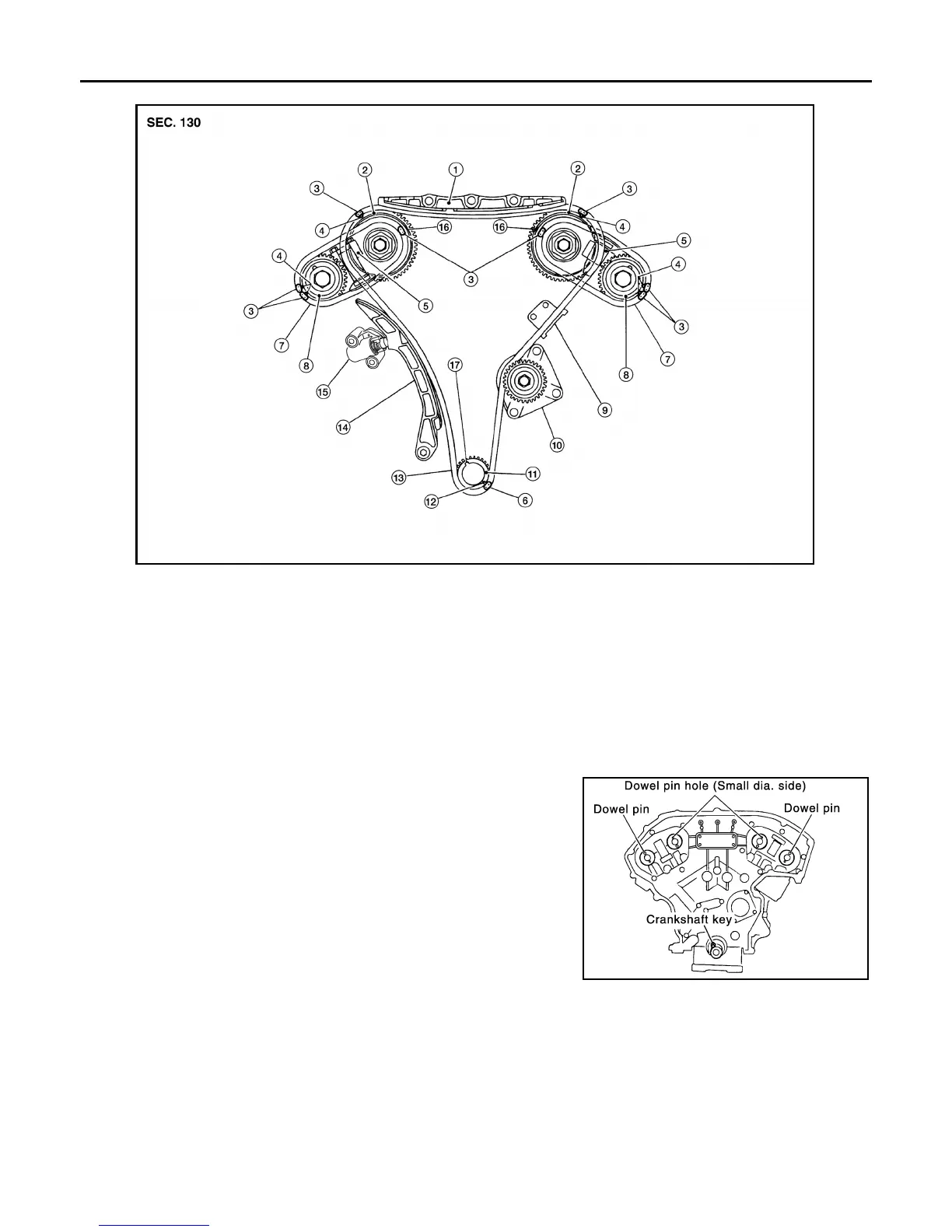
The figure above shows the relationship between the mating mark on each timing chain and that on the corre-
sponding sprocket, with the components installed.
1. Make sure that dowel pin hole, dowel pin of camshaft and crank-
shaft key are located as shown. (No. 1 cylinder at compression
TDC)
NOTE:
Though camshaft does not stop at the position as shown, for the
placement of cam nose, it is generally accepted camshaft is
placed for the same direction as the figure.
CAUTION:
Hole on small diameter side must be used for intake side dowel pin hole. Do not misidentify
(ignore big diameter side).
2. Install timing chains (secondary) and camshaft sprockets as follows:
CAUTION:
1. Internal chain guide 2. Camshaft sprocket (intake) 3. Mating mark (blue link)
4. Mating mark (punched) 5. Secondary timing chain tensioner 6. Mating mark (copper link)
7. Secondary timing chain 8. Camshaft sprocket (exhaust) 9. Tensioner guide
10. Water pump 11. Crankshaft sprocket 12. Mating mark (notched)
13. Primary timing chain 14. Slack guide 15. Primary timing chain tensioner
16. Mating mark (back side) 17. Crankshaft key
Camshaft dowel pin hole (intake side)
: At cylinder head upper face side in each bank.
Camshaft dowel pin (exhaust side)
: At cylinder head upper face side in each bank.
Crankshaft key
: At cylinder head side of right bank.
AWBIA1011GB
KBIA1073E
Revision: January 2013 2013 Xterra