CAMSHAFT
EM-81
< REMOVAL AND INSTALLATION >
[VQ40DE]
C
D
E
F
G
H
I
J
K
L
M
A
EM
N
P
O
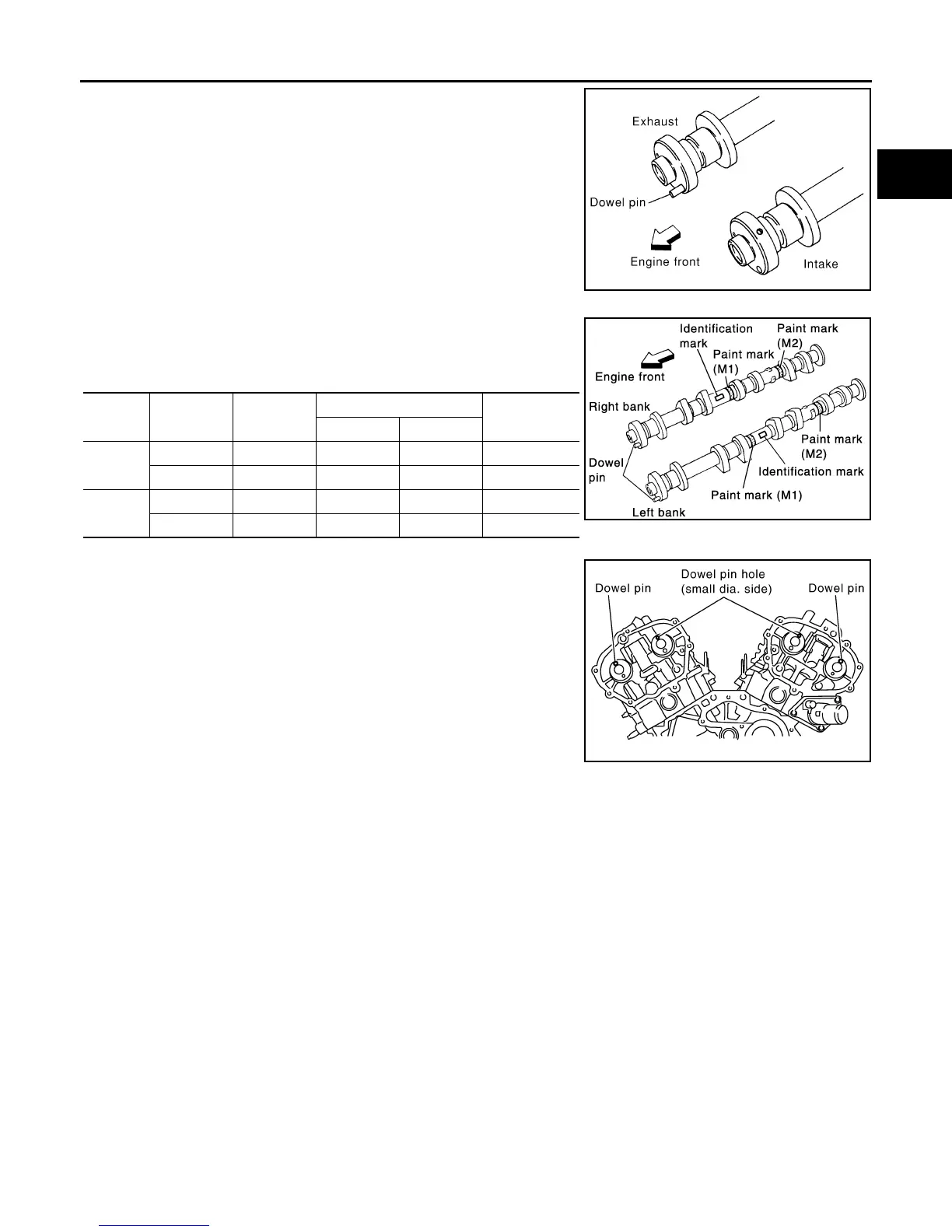
• Install camshaft with dowel pin attached to its front end face on
the exhaust side.
• Follow your identification marks made during removal, or fol-
low the identification marks that are present on new camshafts
for proper placement and direction.
• Install camshaft so that dowel pin hole and dowel pin on front
end face are positioned as shown. (No. 1 cylinder TDC on its
compression stroke)
NOTE:
• Large and small pin holes are located on front end face of
camshaft (INT), at intervals of 180°. Face small dia. side pin
hole upward (in cylinder head upper face direction).
• Though camshaft does not stop at the portion as shown, for
the placement of cam nose, it is generally accepted cam-
shaft is placed for the same direction as shown.
KBIA1071E
Bank INT/EXH Dowel pin
Paint marks
Identification
mark
M1 M2
RH
INT No Green No RE
EXH Yes No White RE
LH
INT No Green No LH
EXH Yes No White LH
KBIA1009E
PBIC2478E
Revision: January 2013 2013 Xterra