Do you have a question about the NIVELCO NIVOCONT K and is the answer not in the manual?
Contains general specifications for the Nivocontrol K conductive level switch.
Details on the electrical and operational parameters of the KRK-622 switching unit.
Technical data for various probe socket types like KSK, KSP, KSH, KLN, KLP.
Information on available product codes and variations for ordering.
List and details of accessories compatible with the Nivocontrol K.
Visual representation of product dimensions for KRK-622 and probe sockets.
Instructions for mounting the switching unit and installing probes.
Shows terminal block assignments and connection examples for KRK-622 units.
Guide to setting delay times, sensitivity, and selecting operating modes.
Explanation of different functions (1-8) for level control and alarms.
Illustrates the operational timing sequences for various functions.
Information on device maintenance, warranty, and repair procedures.
Recommended temperature and humidity for storing the instrument.
The NIVOCONT K KRK-622 is a conductive level switch designed for detecting liquid levels in tanks where the liquid has a specific conductivity greater than 10 µS/cm. This device operates by sensing the resistance between probes, making it suitable for applications where the presence of liquid at a specific level needs to be identified.
The core of the NIVOCONT K system consists of a KRK-622-type switching unit and KLN-2 type probes, which are selected based on the specific application requirements. These probes are connected to the NIVOCONT KS-0 type probe socket heads, which are then screwed into the tank.
For tanks made of non-conductive material or with internal insulation, a dedicated reference probe ('C') must be used in addition to the one, two, three, or four measurement probes. If the tank material itself is conductive, the tank wall can serve as the reference probe.
The conductive switch offers versatile control capabilities. It can be configured for filling-emptying control, utilizing two relay outputs that can operate simultaneously. Alternatively, it can be used for level detection of two independent levels in one or two separate tanks, each with its own independent relay output. The system also supports configurations where multiple level switches share a common reference probe, allowing for various combinations of multiple-probe and single-probe sockets.
The KRK-622 switching unit can be easily mounted on a DIN EN 60715 rail. The KLN-2 probes are designed to be cut to the required length on-site for precise level detection and are then screwed into the KS-0 type sockets. It is crucial to always tighten the probes with an M6 nut to ensure a secure connection. When using KSH-204 type probe sockets, the reference probes require special tightening with SW hexagonal M6 nuts. For multiple probe devices, KLP-201 or KLP-204 type PVDF separators are recommended at every 0.5 m to keep the probes adequately spaced, especially in environments up to +130 °C.
For applications involving pits or wells, a KSK-201 single probe, attached to an insulated cable, can be lowered without the risk of a short circuit. If detection is needed in a well or a plastic pipe, two such probes should be used. Additional probes can be added for detecting more levels.
The wiring configuration depends on the tank's conductivity. If the tank wall is conductive, no reference probe is needed, and the 'C' terminal should be connected to the tank. For multiple probe units, terminals 'E1' and 'E2' are marked with 1-4, while the reference probe is marked 'C'. The permissible cable length between the switching unit and probes is influenced by cable capacitance and liquid conductivity. It's important to note that the terminal block assignments for KRK-622-1 and KRK-622-2 differ, and KRK-622-4 has a distinct assignment. KRK-622-1 and KRK-622-2 do not have an 'S' terminal. Shielded cables are recommended for probes to eliminate signal interferences.
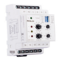
The device provides clear visual indicators for its operational status. A green LED (U) indicates that the unit is powered on. The energized state of the relays is shown by the OUT1 and OUT2 LEDs. If these red LEDs are flashing, it signifies that the timer operation is active. When they light up continuously, it means the corresponding relay is switched on. A yellow LED (FAIL) indicates a probe failure, such as when probe 'E1' is flooded and probe 'E2' is not, which represents an unreal state.
Operating modes, ON delay, and OFF delay can be configured using the DIP switch located on the front panel. The delay times can be adjusted from 0.5 seconds to 10 seconds using the t₁[s] and t₂[s] potentiometers. The sensitivity of the two probes can be set independently using the RE1 or RE2 potentiometers. The sensitivity setting should match the fluid's conductivity. It is advised not to set the sensitivity higher than necessary, as vapor precipitation could lead to operational disturbances. In highly humid environments, insulated probes should be used. The ON Delay / OFF Delay switch on the DIP switch allows selection of the relay delay type (switch-on delay or switch-off delay).
The DIP switch allows users to select the desired function. The upper three switches determine the function number, while the fourth switch selects between ON delay or OFF delay. The minimum delay time is 0.5 seconds, set via the potentiometers.
The NIVOCONT K KRK-622 is designed for minimal maintenance and does not require regular servicing. However, if the device needs to be returned for repairs, it must be thoroughly cleaned beforehand. Any parts that have come into contact with the medium must be decontaminated due to potential harmful substances. An official "Returned Equipment Handling Form" must be completed, enclosed with the parcel, and downloaded from the manufacturer's website. The device must be returned with a declaration of decontamination, confirming that the decontamination process has been successfully completed and that the device is free from any hazardous substances.
| Operating temperature | -40…+150 °C (-40…+302 °F) |
|---|---|
| Output | Relay |
| Wetted parts material | Stainless steel |
| Approvals | ATEX, IECEx |
| Contact Configuration | SPDT |