1 pmg511en23q03
Thank you for choosing a NIVELCO product!
Alarm output Relay (AL1) 250 V / 3 A AC-1
Optional
outputs
Transmitter
output
4…20 mA: output accuracy ±0.3% F.S
(max. loop resistance 500 Ω)
Communication RS485 communication Modbus RTU protocol
Control algorithms: ON/OFF, P, PI, PD, PID
Hysteresis RTD / Thermocouples: 1…100 °C (0.1…100 °C) (33.8…212 °F [32.2…212 °F])
Proportional band (P) 0.1…999.9 °C (32.2…1 831.8 °F) (0.1…999.9%)
Integral time (I)
0…9999 s
Differential time (D)
Control period (T)
Relay output, SSR driver output: 0.1…120.0 s
Current loop output + SSR driver output: 1.0…120.0 s
Manual reset value 0…100%
Sampling period 50 ms
Vibration resistance
0.75 mm (0.03″)amplitude at frequency 5 to 55 Hz (for 1 min)
in each X, Y, Z direction for 2 hours
Relay life
cycle
Mechanical
OUT1/OUT2: min. 5,000,000 operations
AL1: min. 20,000,000 operations
Electrical OUT1/OUT2, AL1: min. 100,000 operations
Memory retention ~10 years (non-volatile semiconductor memory)
Ingress protection Behind mounting plane: IP20, front panel: IP54
Insulation type
Reinforced insulation between the input and the power part
(dielectric breakdown: 2 kV)
Bounding box size 48 × 48 × 70.5 mm (1.89 × 1.89 × 2.77″)
Weight ~105 g (3.7 oz)
2.2 ACCESSORIES
– Quick Setup Guide
– Mounting bracket
– Warranty Card
– EU Declaration of Conformity
2.4 OUTLINES AND DIMENSIONS
The device can be mounted in a 48×48 mm (1.8 × 1.8″) cutout (1/16 DIN board instrument).
The insertion depth is 64.5 mm, other main dimensions are shown in the gure.
PMG–5
Front Side
45
1.7
Mounting Bracket
31
20
15
21
5
45
16
48.6
44.9
36
55
56
3. Mounting
The panel is mounted on the front panel in a 1/16 DIN (48 × 48 mm [1.8 × 1.8″]) cutout with the supplied mounting
frame. Make sure that the rubber seal ts, which ensures tightness from the front. When installing multiple instru-
ments, ensure adequate distances. Insert the unit into the bracket panel and secure the bracket with a straight
screwdriver.
(-)
Tightening the mounting bracket
Minimum distance between devices
A – min. 65 mm (2.55″) C – 45
0
+0.6
mm
B – min. 65 mm (2.55″) D – 45
0
+0.6
mm
D
B
C
A
4. WIRING
DI-1
RS485 (B
-
)
RS485 (A+)
RTD TC Sensor
CT
1
2
3
4
5
6
7
8
9
10
11
13
14
15
16
17
18
A
B
B'
V
mA
mA
DI-1
-
+
Digital input,
Non-contact,
Contact input
V
mA
*
Supply voltage
100…240 V AC 50/60 Hz 8 VA
24 V AC 50/60 Hz 8 VA
24…48 V DC 5 W
V
mA
DC Current
0/4…20 mA
Max. load 500 Ω
SSR
11 V DC ±2 V
Max. 20 mA
AL1 output
250 V 3 A AC–1
Resistive load
Output 2
Relay
250 V 3 A AC–1
Resistive load
Current
transformer (CT)
0.0…50.0 A
Transmitter
output
4…20 mA
DC
12
Output 1
Relay
250 V 3 A AC–1
Resistive load
*
*
Ally types have colored connection points ( ). Other connection point types depend on the particular variant.
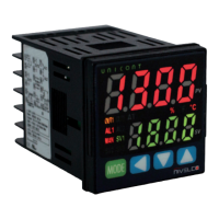
UNICONT PM
PMG–500
UNIVERSAL CONTROLLER
Manufacturer:
Process Control Co.
H–1043 Budapest, Dugonics u. 11.
Tel.: +36-1-889-0100
E-mail: sales
@
nivelco.com
nivelco.com
QUICK SETUP GUIDE
3
rd
edition
PDF
1. INTRODUCTION
In addition to the 1/16 DIN (48 × 48 mm [1.8 × 1.8″]) design, the UNICONT PM universal controller family is characterized by easy setpoint adjustment and
easy programming. The universal analog PID controller is suitable for processing signals from Pt100 resistance thermometers, various thermocouples,
and transmitters with a 4…20 mA and 0…10 V DC, 0…5 V DC, 1…5 V DC, 0…100 mV DC signal. The control output can be a relay, a continuous 0…20 mA
or 4…20 mA current signal, or an output suitable for operating an SSR (solid-state relay). The self-learning autotuning (AT) mode helps users determine
PID parameters. The device provides automatic wire compensation for the Pt100 input signal and automatic cold junction compensation for the thermo-
couple input signal. Some PM–500 series members are also capable of RS485 communication.
The UNICONT PM–500 enables more efcient control with a super-fast 50 ms sampling cycle and ±0.3% display accuracy. Moreover, it supports a variety
of control modes, including simultaneous control of heating and cooling and automatic/manual control and communication functions.
2. SPECIFICATIONS
2.1 GENERAL DATA
PMG–500
Power
supply
AC 100…240 V AC, 50/60 Hz, 8 VA
AC/DC 24 V AC 50/60 Hz, 8 VA / 24…48 V DC, 5 W
Voltage tolerance ±10% deviance from nominal voltage
Ambient temperature –10…+50 °C (14…122 °F)
Ambient humidity 35...85% RH
Display
Process Value (PV): 7-segment, red, 7.0 × 14.0 mm (0.27 × 0.55").
Set Value (SV): 7-segment, green, 5.0 × 10.0 mm (0.2 × 0.39″).
Status LEDs with labels
Primary
input
RTD mode Compatible resistance temperature sensors: JPt 100 Ω, DPt 100 Ω, DPt 50 Ω, Cu 100 Ω, Cu 50 Ω, and Nikel 120 Ω
TC mode Compatible thermocouple sensors: K, J, E, T, L, N, U, R, S, B, C, G, and PLII
Analog mode
Voltage: 0…100 mV, 0…5 V, 1…5 V, 0…10 V
Current: 0…20 mA, 4…20 mA
Optional
inputs
CT input 0…50 mA (for external 1/1000 CT connection)
Digital input (DI)
Active input for passive switches, measuring current: 0.5 mA / 5 V
Contact switch – sensing threshold: ’On’ < 2 kΩ / ’Off’ > 90 kΩ
Transistor switch – sensing threshold: ’On’ < 1.0 V DC / ’Off’ < 0.1 mA
Display
accuracy
RTD mode
Room temperature (23 °C ±5 °C): (PV ±0.3% or ±1 °C) ±1 digit
Full ambient-temperature range: (PV ±0.5% or ±2 °C) ±1 digit
TC mode
Analog mode
Room temperature (23 °C ±5 °C): ±0.3% F.S. ±1 digit
Full ambient-temperature range: ±0.5% F.S. ±1 digit
CT input ±5% F.S. ±1 digit
Control
outputs
Relay (OUT1/2) 250 V / 3 A AC-1
SSR (OUT1/2) 11 V DC ±2 V / 20 mA
Current (OUT1/2)
4…20 mA / 0…20 mA selectable (max. loop resistance 500 Ω)