Do you have a question about the NIVELCO UNICONT PMG-500 and is the answer not in the manual?
Provides general specifications for the UNICONT PM controller, including power, voltage, and environmental conditions.
Lists the included accessories with the UNICONT PM controller, such as the manual and mounting bracket.
Explains the coding system used to specify different UNICONT PM controller configurations based on input and output.
Details the physical dimensions and cutout requirements for mounting the UNICONT PM controller.
Describes the panel mounting procedure for the UNICONT PM controller using the supplied mounting frame.
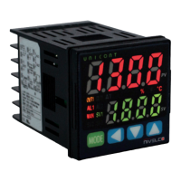
Identifies the key components of the UNICONT PM controller's front panel display and buttons.
Explains the initial power-on sequence and behavior of the UNICONT PM controller.
Details how to configure the universal input type for various sensors and signals.
Lists supported input types like thermocouples, RTDs, voltage, and current with their specifications.
Describes how to set the temperature unit (°C or °F) for sensor inputs.
Explains setting the input range and display scale for analog input signals.
Sets the lower limit for analog input scaling and temperature range.
Sets the upper limit for analog input scaling and temperature range.
Configures the decimal point position for measured and set values.
Sets the display scale for the lower limits of analog input.
Sets the display scale for the upper limits of analog input.
Corrects sensor offset errors for thermocouples, RTDs, and analog inputs.
Stabilizes the Process Value (PV) by filtering rapid input signal changes.
Limits the Set Value (SV) range within the sensor or analog input limits.
Allows selection between current loop, SSR, or relay control outputs.
Configures the SSR function for specific control output types.
Sets the upper and lower range for current loop output (4-20 mA or 0-20 mA).
Configures the controller for either heating-only or cooling-only operation modes.
Sets up the controller for simultaneous heating and cooling control.
Defines deadband or overlap band between heating and cooling control for smoother operation.
Sets the upper and lower limits for the Manipulated Variable (MV) output.
Configures the controller's output behavior upon detecting a sensor break error.
Configures ramp rate for gradual changes in setpoint (SV) to prevent sudden temperature shifts.
Explains how to switch the controller between automatic and manual operating modes.
Sets the initial Manipulated Variable (MV) value when switching to manual control.
Sets a preset manual MV value for manual control operations.
Selects the temperature control method, such as PID, ON/OFF, or heating/cooling.
Configures ON/OFF control with hysteresis for stable temperature regulation.
Adjusts ON/OFF points for hysteresis in ON/OFF control mode.
Details PID control parameters for precise temperature regulation.
Sets the proportional band for heating and cooling PID control.
Configures the integral time for heating and cooling PID control.
Sets the derivative time for heating and cooling PID control.
Sets the control period for heating and cooling, affecting output switching.
Corrects stable temperature differences (offset) using manual reset.
Enables or disables the automatic tuning feature to determine PID constants.
Selects the auto-tuning mode (TUN1 or TUN2) for PID tuning.
Configures the basic operation mode for alarms (e.g., deviation, absolute value).
Sets an alarm when the Process Value (PV) exceeds an upper absolute limit.
Sets an alarm when the Process Value (PV) falls below a lower absolute limit.
Detects and alarms for a break in the control loop.
Triggers an alarm when a sensor connection is lost.
Alarms for a fault in the heater's power supply or connection.
Selects how alarms behave, such as standard, latched, or standby sequence.
Sets the specific values for upper and lower alarm limits.
Sets the hysteresis for alarm output to prevent rapid switching.
Configures the alarm output relay as Normally Open (NO) or Normally Closed (NC).
Sets delays for alarm output and indicators to avoid false alarms.
Diagnoses control loop integrity by monitoring temperature changes and detecting loop breaks.
Sets the monitoring time for the Loop Break Alarm (LBA).
Defines the deviation band used for detecting Loop Break Alarms (LBA).
Triggers an alarm if the sensor is disconnected during temperature control.
Detects heater power supply faults using a current transformer (CT).
Sets the reference value for detecting heater burnout.
Configures deactivation of alarm outputs via digital input or button.
Configures the output value for analog transmission (e.g., PV, SV).
Sets the upper and lower limit values for analog transmission output.
Assigns unique addresses to controller units for communication.
Sets the data transfer rate (baud rate) for communication.
Configures the parity bit for data error checking during communication.
Sets the number of stop bits to indicate the end of a data series.
Configures the timeout for communication responses to prevent errors.
Enables or disables parameter modification via communication.
Displays the current heating Manipulated Variable (MV).
Displays the current cooling Manipulated Variable (MV).
Monitors and displays the current of the controlled heater load.
Controls the start and stop of the controller's output functions.
Sets the output value when the controller is in STOP mode.
Enables or disables the alarm output when the control is stopped.
Manages multiple Set Values (SVs) for different operating points.
Sets the quantity of multiple Set Values (SVs) the controller can manage.
Selects which of the configured Multi SVs is currently active.
Configures the specific values for each Multi SV.
Assigns functions to the digital input terminal DI-1.
Assigns functions to the digital input buttons on the front panel.
Restricts parameter access based on user level (standard or high).
Locks SV parameters to prevent modification.
Locks specific parameter groups to prevent modification.
Resets all controller parameters to factory defaults.
Secures parameter access by setting up a password.
Guides through setting up a password for parameter access protection.
Provides instructions for resetting a lost password.
| Operating Temperature | -20°C to +60°C |
|---|---|
| Protection | IP65 |
| Application | Level measurement and control |
| Output | 4-20 mA |
| Power Supply | 230 V AC or 24 V DC |
| Housing Material | Plastic |
| Material | Not applicable |