7
2 UNPACKING AND ASSEMBLY
2.1 CHOOSING THE RIGHT LOCATION
We recommend unpacking and assembling the wing on a training hill or
a at clear area without too much wind and free of obstacles. It will help
you to carry out all the recommended steps required to check and inate
the LINK 2.
We recommend the whole installation procedure is supervised by a
qualied professional instructor or ofcial dealer. Only they can address
any doubts in a safe and professional way.
2.2 PROCEDURE
Take the paraglider out of the rucksack, open and unfold it on the ground
with the lines positioned on the undersurface, oriented in the direction
of ination. Check the condition of the fabric and the lines for defects.
Check the maillons/IKS connecting the lines to the risers to make sure
they are fully closed and tightened. Identify, and if necessary untangle,
the A, B and C-lines, the brake lines and corresponding risers. Make sure
that there are no knots.
2.3 ASSEMBLY WITH THE ENGINE
After carefully laying out the wing connect the risers to the harness/
engine according to the paramotor manufacturer instructions and set the
trimmers to the neutral position.
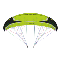
The LINK 2 risers are colour-coded:
- Right: green
- Left: red
This colour-coding makes it easier to connect the wing to the correct
side and helps prevent pre-ight errors.
Correctly connect the risers to the attachment points so that the risers
and lines are correctly ordered and free of twists. Check that the IKS and
carabiners are properly fastened and securely locked.
2.4 HARNESS TYPE
Check the engine manufacturer’s specication on attachment points.
Before any ight commences it is strongly recommended that the pilot
checks the connection of the wing to the harness/engine and whilst
seated in the harness checks the length of the brake lines, that they can
easily reach the handles and also easily reach and operate the trimmers
on both sides. The LINK is delivered with two brake height options so the
pilot can choose their optimal the brake position.
2.5 SPEED-BAR
The speed-bar is a means of temporary acceleration by changing the
ow over the prole. The speed system comes pre-installed on the risers
and is not modiable as it conforms to the measurements and limits
stipulated in its certication.
The LINK 2 includes a speed system with with a differential between the
A-D risers of 8.5 cm.
The speed system is engaged when the pilot pushes the speed-bar - not
included as standard with this glider model - with their feet (see 2.5.1
Speed system assembly)
The speed system uses an action/reaction system. Released, the speed-
bar is set to neutral. When the bar is pushed using the feet, the wing
accelerates. The speed can be regulated by varying the pressure on the
bar. Once the pressure on the bar is released, the speed system returns
to the neutral setting.