16
nixiediy@gmail.com
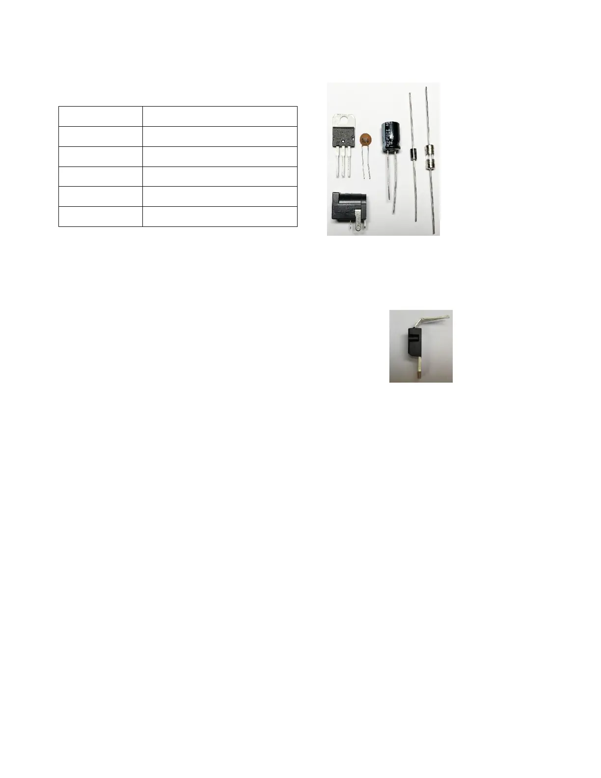
2. Low Voltage Power source components preparation for insertion into the board
and soldering order
5.5mm x 2.1mm PCB DC Jack
2.1. Bend U1 integrated circuit leads.
2.2. Bend the two leads of the fuse and diode D1 so that they form a right angle to the component
body.
2.3. To install, place the leads of the component through the appropriate holes and press the
component down against the component side of the PCB.
2.3.1. The small-value ceramic capacitor (C7) may be installed in either orientation, but the larger-
value cylindrical capacitor (C1) must be installed with the proper polarity. The polarity is indicated on
the PCB by a “+” sign near one end of the capacitor location. The polarity is indicated on the body of
the capacitor with a stripe with a minus (-) sign located on the negative side of the capacitor. In
addition, the shorter lead is the negative lead.