28
nixiediy@gmail.com
10.1. Resistor R17, R18, R19 leads bend in accordance with item 3.1. Insert them into location R17,
R18, R19 and solder it’s leads as pointed on the picture.
10.2. Install the transistor Q3, Q4, Q5 legs into the board holes marked as Q3, Q4, Q5 that its case flat
edge is above the flat edge of the placement marking. Solder it leads.
10.3. Cut the desired number of pins and solder them into position J2.
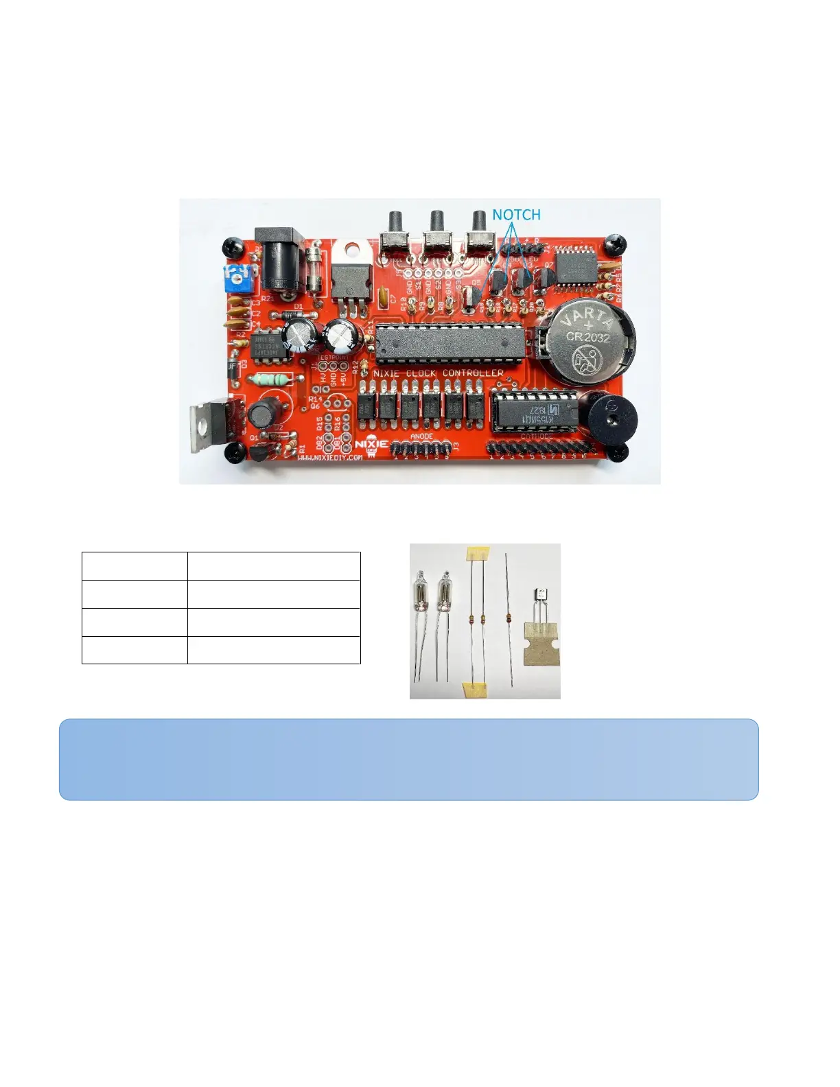
11. Neon dot circuit components
11.1. Resistors R14, R15 and R16 leads bend in accordance with item 3.1. Insert them into locations
R14, R15, R16 and solder their leads as pointed on the picture.
11.2. Install the transistor Q6 legs into the board holes marked as Q6 that its case flat edge is above
the flat edge of the placement marking. Solder it each leg in accordance with sub-item 10.2
directions.
11.3. Cut the desired number of pins and solder them into position DB1, DB2.
NOTE: Resistors R15, R16 are selected for standard neon bulbs that are included in the KIT. If
necessary, connect other neon bulbs, select the appropriate resistors.