FEATURES
The EM35-50 features a 6-digit Manager code and up to 9 user codes. Entering a valid code
starts a 3 second window for unlocking, allowing the lock bolt to be retracted by turning either
a rotating keypad or a knob, as on the EasyTouch ET20•xx. The safe boltwork can then be moved
into the OPEN positon. After restoring the safe boltwork to the fully LOCKED positon and extending
the lock bolt by rotating the keypad or knob CCW, the EM35•50 automatically secures.
MOUNTING INSTRUCTIONS
The EM35•50 may be mounted in any of the four mounting directions (LH, RH, VU or VD).
Mounting dimensions are industry standard.
Temporarily secure the lock body to the mounting surface with supplied mounting screws.
Insert the grooved spindle shaft through from the face of the door until it bottoms out in the lock body.
Ensuring that any adapter or trim plates are in place, use the included measuring device to mark the spindle for cutting.
The spindle must extend .24” from the mounting surface of the keypad after cutting to properly engage with the chosen
keypad. Deburr/square the cut end of the spindle. Unmount the lock body.
Insert the spindle into the chosen keypad and press the wire into the groove in the spindle.
Feed the cable though the hole in the door, then follow separate instructions for keypad mounting.
With the lock body in hand, feed the keypad cable connector through the square opening on the underside of the lock
case. Holding the cable straight, place the lock body over the grooved spindle and screw it securely to the mounting
surface. Use only the supplied 1⁄4-20 (or M6) screws to mount the lock. Tighten the screws securely so the lock body
is firmly attached to the flat mounting surface. Use of screw locking glue (i.e. LocTite) is recommended). Insert the
connector from the keypad into the outer lock housing receiver labeled ENT. Ensure that the connector is fully seated. To
remove the connector, carefully lift and pull away from the lock body. To secure the cable, push it into the square groove
on the lock cover. Secure any excess away from moving parts.
ELECTRONICS TEST
Like all NL Locks, the Straight Bolt includes Function 5 - a unique feature to test
for proper functioning of the electronics:
• Press and hold 5 until double beep and the LED stays on
• Enter all keys in numerical sequence: 1-2-3-4-5-6-7-8-9-0
• A double beep at each key press indicates that the lock and keypad
are communicating and performing properly
• A long signal indicates a fault that can likely be corrected by replacing the keypad
FUNCTIONAL TEST (With door OPEN)
Enter valid code or factory code (5-5-5-5-5-5), double beep = valid entry
• Rotate keypad or knob CW to retract lock bolt
• The bolt must move freely
• Turn boltwork handle to OPEN position
• Turn boltwork handle to the LOCKED position
• Rotate keypad or knob CCW to extend lock bolt
• The bolt must fully extend and secure
• Ensure that there is at least 1/16” clearance on ALL
sides of the lock bolt when the safe boltwork is
in the fully LOCKED position
IMPORTANT: Repeat the functional test several times
before locking the safe door!
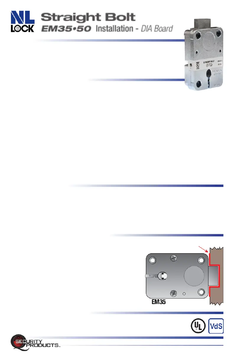
BOLTWORK REQUIRMENTS
In the LOCKED position, the required distance between the lock bolt
and the cavity in the movable boltwork must be a minimum of 1/16”
Straight Bolt EM35•50 INSTALLATION • Rev. 2402A MT • © 2024 QSecurity Industries
QSecurityProducts.com • 1014 S. Main Street • Nicholasville, Kentucky 40356 • 859.241.2063
UL Type 1
VdS EN1300 Class B
min.1/16”
(1.5mm)
REQUIRED
CLEARANCE
Straight Bolt
EM35•50 Installation - DIA Board
 Loading...