Do you have a question about the Nokia 6300 RM-217 and is the answer not in the manual?
Details network bands for RM-217 and RM-222 models.
Lists camera, display, OS, Bluetooth, and FM stereo radio features.
Covers talk/standby times and lead-free soldering information.
Explains the manual's intent and confidentiality for service technicians.
Lists important safety warnings for operation and servicing procedures.
Details necessary precautions to prevent ESD damage to components.
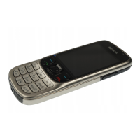
Detailed breakdown of phone parts with labels and reference numbers.
Identifies screws, clips, and other small assembly components.
Lists components associated with the front cover assembly.
Details parts included in the back cover assembly.
Identifies internal modules like antenna, camera, and speaker.
Categorizes phone components by material for proper disposal.
Provides advice for sorting waste into recyclable fractions.
Illustrates the main PCB with labelled solder components for Level 2 servicing.
Describes FLS-5 flash dongle and ACF-8 universal power supply.
Lists travel charger AC-4 and internal battery BL-4c.
Details camera removal, service cable, and alignment jig tools.
Covers RJ-148 soldering jig and lead-free solder wire.
Describes the NMP Standard Toolkit (V2) for service operations.
Explains the FLS-5 based SW update process and required hardware.
Lists tools, prep steps, and covers removal.
Details screw removal and emphasizes SD card removal.
Instructions on unlocking A-COVER clips using SRT-6.
Steps for lifting covers, removing keymat, and internal screws.
Instructions for display protection and separating screws.
Steps for display film, B-COVER, and camera gasket removal.
Guidance on removing camera module and flex shielding lid.
Steps for UI shield, LCD connector, and protective film removal.
Separating parts and removing microphone and DC jack.
Instructions for earpiece, plastic chamber, and IHF speaker removal.
Guidance on releasing side window clips and removing keys.
Steps for releasing label cover and opening SIM lid.
Guidance on releasing latches and final clips.
Image showing all disassembled parts signifying completion.
Shows component layout and emphasizes correct label cover assembly.
Instructions for inserting label cover and securing latches.
Steps for LED/window insertion and speaker contact checks.
Securing chamber clips and using new flex shielding lid.
Guidance on replacing the camera, minding the guiding tab.
Ensures micro SD card is not inserted before placing assembly onto B-COVER.
Details correct screw tightening and torque application for covers.
Explains the meaning of icons used in the quick trouble shooter sections.
Details the fault numbering system and symptom description format.
Guides through troubleshooting steps for power-on issues.
Instructions on measuring the 4-pole switch state.
Steps to diagnose and resolve charging problems.
Identifies components relevant to charging faults.
Guides through diagnosing and fixing "No Service" issues.
Identifies components related to "No Service" faults.
Steps to diagnose and resolve issues with the earpiece.
Identifies components relevant to earpiece faults.
Guides through diagnosing and fixing "IHF Speaker" problems.
Identifies components relevant to IHF speaker faults.
Steps to diagnose and resolve display-related issues.
Identifies components relevant to display faults.
Guides through diagnosing and fixing microphone problems.
Identifies components relevant to microphone faults.
Steps to diagnose and resolve issues with the keymat.
Identifies components relevant to keymat faults.
Guides through diagnosing and fixing AV connector problems.
Identifies components relevant to AV connector faults.
Steps to diagnose and resolve issues with the volume keys.
Instructions on measuring the 4-pole switch for volume keys.
Guides through diagnosing and fixing card reader problems.
Identifies components relevant to card reader faults.
Steps to diagnose and resolve camera-related issues.
Identifies components relevant to camera faults.
| Network Technology | GSM |
|---|---|
| 2G bands | GSM 850 / 900 / 1800 / 1900 |
| GPRS | Class 10 |
| EDGE | Class 10 |
| Status | Discontinued |
| SIM | Mini-SIM |
| Type | TFT, 16M colors |
| Phonebook | 1000 entries |
| Call records | 20 dialed, 20 received, 20 missed calls |
| Internal | 7 MB |
| Primary | 2 MP |
| Alert types | Vibration; Downloadable polyphonic, MP3 ringtones |
| Loudspeaker | Yes |
| 3.5mm jack | No |
| WLAN | No |
| Browser | WAP 2.0/xHTML |
| Games | Yes + Downloadable |
| Java | Yes, MIDP 2.0 |
| Battery | Removable Li-Ion 860 mAh battery (BL-4C) |
| Stand-by | Up to 348 h |
| Talk time | Up to 3 h 30 min |
| Resolution | 240 x 320 pixels |
| Memory Card slot | microSD (dedicated slot) |
| Bluetooth | v2.0, A2DP |
| Radio | Stereo FM radio |
| Messaging | SMS, MMS, Email |
| Colors | Black, Silver, Red |
| Dimensions | 106.4 x 43.6 x 11.7 mm, 56 cc (4.19 x 1.72 x 0.46 in) |
| Size | 2.0 inches, 31 x 41 mm (~24.4% screen-to-body ratio) |