After Sales
Technical Documentation
Installation Instructions
Page 14
Original 18/96
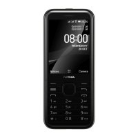
CAR
RADIO
Bosch P/N 0–332–204–150
12 V, 30 A. SPDT
12 V d.c.
12 V d.c.
Supply for
car radio
Fuse 200 mA
(not supplied)
To XCRM line
(yellow wire)
85
87
87A
30
86
GND
Another possibility is to use a special muting unit, which mutes the radio by
connecting load resistors to the speaker lines of the car radio.
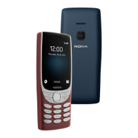
Antenna Motor Control AMC
The antenna motor control offers a feature, green wire of the system cable
(AMC), that may be used to control different devices on and off. The voltage in
this output is +12 V whenever the phone is on. If the phone is turned off, the
voltage disappears. The maximum output current is 200 mA, therefore for ex-
ample motorized antenna must be controlled via a relay, see picture below.
87
Bosch P/N 0–332–204–150 12 V, 30 A. SPDT
12 V d.c.
Fuse 1 A
85
87A
30
86
GND
CONTROLLED
DEVICE e.g.
MOTOR ANTENNA
GND
Supply for device
From AMC line (green wire)
All installations should take into account any special requirements of the cus-
tomer. However, should the customer require an installation that is illegal or
unsafe these facts must be pointed out to the customer and a policy of non–
compliance adopted.
Testing
Once installed, the equipment should be tested to ensure that it is operating
satisfactorily and that the position of the units does not impair on the driver’s
ability to control and operate the vehicle in any way.
Use the phone to make a call when the vehicle is parked with the engine run-
ning. During the call, switch off the engine. Ensure that the phone is operational
with the engine running and with the engine switched off. For operating in-
formation refer to the ’Owner’s Manual’ supplied with the phone.

 Loading...