Do you have a question about the Nokia Asha 230 RM-986 and is the answer not in the manual?
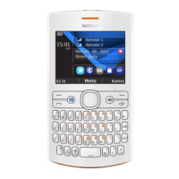
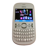
Details components of the A-COVER assembly.
Components related to the light swap package.
Components of the D-COVER assembly and related parts.
Tool preparation, protection, battery cover, and screw removal steps.
Releasing D-COVER, antenna, speaker, display, and A-COVER.
Removing earpiece, display, camera, label, and completing disassembly.
Instructions for fastening screws to a specific torque value.
Identification of components on the top side of the printed circuit board.
Identification of components on the bottom side of the printed circuit board.
Details service cables and adapters like CA-101 and AC-18.
Information on specialized tools like the SS-276 camera removal tool.
Details on Nokia Standard Toolkit (v2) and tool re-ordering.
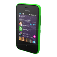
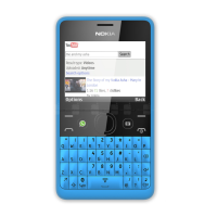
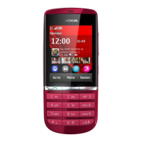
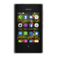
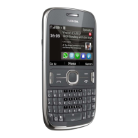
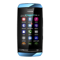
Identifies controls and connectors on the front and top of the device.
Identifies controls and connectors on the rear and side of the device.
Illustrates the concept of flashing service software onto the device.
| Model | Nokia Asha 230 RM-986 |
|---|---|
| Network | GSM |
| 2G bands | GSM 850 / 900 / 1800 / 1900 |
| GPRS | Yes |
| EDGE | Yes |
| Announced | 2014, February |
| SIM | Single SIM (Mini-SIM) or Dual SIM (Mini-SIM, dual stand-by) |
| Alert types | Vibration; MP3, WAV ringtones |
| Loudspeaker | Yes |
| 3.5mm jack | Yes |
| Card slot | microSD, up to 32 GB |
| Call records | Yes |
| RAM | 64 MB |
| Main Camera | 1.3 MP |
| Video | Yes |
| Radio | Stereo FM radio |
| USB | microUSB 2.0 |
| Messaging | SMS, MMS, Email, IM |
| Browser | WAP 2.0/xHTML, HTML |
| Games | Yes |
| Java | Yes, MIDP 2.1 |
| Stand-by | Up to 504 h |
| Talk time | Up to 12 h |
| Music play | Up to 41 h |
| Processor | 1.0 GHz |
| Status | Available |
| Weight | 89.3 g (3.14 oz) |
| Display Type | TFT |
| Display Size | 2.8 inches |
| Resolution | 240 x 320 pixels |
| Phonebook | Yes |
| Battery | 1200 mAh |
| Colors | Black, White, Cyan, Yellow |
| Operating System | Asha Software Platform |