EasyManua.ls Logo

nologo START-S5PV User Manual

nologo START-S5PV
20 pages
To Next Page IconTo Next Page
Page #1 background imageLoading...
Page #1 background image
START-S5PV
• Single-phase control unit for one motor 230 / 400 opto-isolated
• For rapid doors or roll up doors
• Automatic time counter, 4 functions, bush function.
Manual for the installer
START-S5PV_230/400_281113_VXX17_GB www.ebtechnology.it www.nologo.info
Opening contactor
Closing contactor
Common contactor
Brake/Light COM
Brake/Light OLS NA
Brake/Light CLS NC
Lamp
Lamp
-11-
-10-
- 9 -
- 8 -
- 7 -
- 6 -
- 5 -
- 4 -
0 Vac
- 1 -
230 Vac
- 2 -
400 Vac
- 3 -
Test
Test
Common
Common
Common
Photo-beam close
Stop
Services (input for safety edge)
Pedestrian
Start
24 Vac
24 Vac
-19-
-18-
-17-
-16-
-15-
-14-
-13-
-12-
-22-
-21-
-20-
-24-
-23-
Common
-24-
Antenna
Opening limit-switch
-26-
Input for opening control
-28-
Input for closing control
-29-
Closing limit switch
-27-
BRAKE
Passive brake: In case of lack of tension the brake works
DIP 1 B - OFF (Par.no 4.4)
Output for lamp with
or without card
(DIP7)
4
6
5
6
4
5
6
Opening
remote-control
switch
Closing
remote-control
switch
TX RX
OUT24 Vac
Photocells working
in closing
N.C.
N.C.
N.O.
N.O.
N.O. N.O.
N.C.
24 Vac
Light
Light
-30-
-32-
-31-
Man present open
-33-
Man present close
With this connection the
“man present” is always
activated
This connection shows that
the “man present” is activated
with STOP function
32 33 34
N.O. N.O.
32 33 34
N.O. N.O.
16 17 18
230/400 Vac
Question and Answer IconNeed help?

Do you have a question about the nologo START-S5PV and is the answer not in the manual?

nologo START-S5PV Specifications

General IconGeneral
Brandnologo
ModelSTART-S5PV
CategoryControl Unit
LanguageEnglish

Summary

1 Introduction

1.1 Safety precautions

General safety measures for installation and use of the control unit.

1.7 Connections Notes

Provides critical notes for safe electrical connections and component protection.

2 Installation of the control unit

2.1 Description of the electrical connections

Detailed description of terminal board connections and their respective functions.

2.2 Scheme of the control board

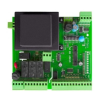
Visual representation of the control board layout and LED indicator functions.

2.3 Connection of the TENSION

Instructions for connecting the 230 Vac or 400 Vac power supply to the control unit.

2.6 Connection of a CONTACTOR

How to correctly connect the opening and closing contactors for motor control.

2.8 Connection of the PHOTO-BEAM

Wiring instructions for connecting the photo-beam safety sensor.

2.9 Connection of the PHOTO-BEAM with PHOTO-TEST

How to connect the photo-beam with the PHOTO-TEST function enabled via DIP A.

2.10 Connection of STOP devices

Wiring instructions for connecting safety stop buttons or normally closed contacts.

3 Functions and adjustment

4 Installation of the plug-in receiver and managing of the REMOTE CONTROL

5 Turn on and program of the control unit