Do you have a question about the Norac John Deere 4720 and is the answer not in the manual?
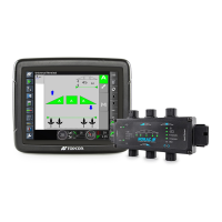
Visual overview of electronic component layout for installation.
Diagram showing the hydraulic circuit connections and fittings.
Comprehensive list of all components included in the installation kit.
Specific components and quantities for the 44865-36 hydraulic fitting kit.
Specific components and quantities for the 44865-38 hydraulic fitting kit.
Step-by-step guide for assembling the hydraulic valve block.
Instructions for securely mounting the valve block onto the sprayer.
Procedures for installing the hydraulic roll cylinder onto the boom.
Steps for connecting hydraulic hoses and fittings to the system.
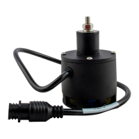
Guidelines for optimal placement and orientation of ultrasonic sensors.
Best practices for mounting sensor brackets to minimize issues.
Specific steps for installing a three-sensor configuration.
Specific steps for installing a five-sensor configuration (severe terrain).
Instructions for installing the sensor on the main lift assembly.
Procedure for installing the HCM1 module and its connections.
Connecting various cables for sensors and system components.
Schematic for a 1m, 14 AWG network cable (C01).
Schematic for a 3m, 14 AWG network cable (C02).
Schematic for a 20m, 18 AWG network cable (C05).
Schematic for a valve cable connecting 4-pin to 2-pin DT connectors (C10).
Schematic for a temperature probe and bypass cable (C11).
Schematic for the SC Main Interface JD cable (C15).
Schematic for the JD 30 Series interface cable (C20).
Schematic for the fused battery connection cable (C30).
| Brand | Norac |
|---|---|
| Model | John Deere 4720 |
| Category | Control Systems |
| Language | English |