Do you have a question about the Norcold 1200 Series and is the answer not in the manual?
Provides maintenance, diagnostic, and repair information for Norcold refrigerators.
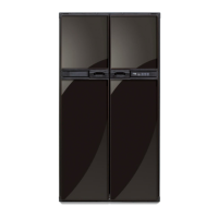
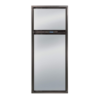
Explains the 2-way refrigerator models and factory-installed accessories.
Details the location and content of the refrigerator's information label.
Specifies the location of the cooling unit's unique serial number.
Lists relevant standards and certifications for the refrigerators.
Outlines requirements for proper refrigerator installation.
Recommends using only authorized Norcold replacement parts for safety.
Provides contact information for technical support.
General safety precautions and disclaimer for servicing.
Explanation of warning and caution alert symbols.
Critical safety warnings regarding LP gas, electrical, and unit operation.
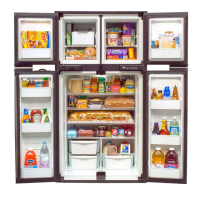
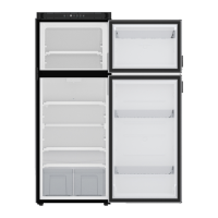
Details freezer and fresh food compartment capacities.
Provides installation dimensions for the refrigerator enclosure.
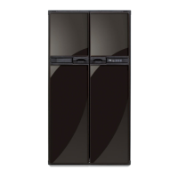
Specifies dimensions for decorative door panels.
Details control type, temperature settings, and sensor.
Maximum tilt angles permitted for side-to-side and front-to-back operation.
Covers operating voltage, fuse, and amp draws.
Details operating voltage, fuse, and power rating.
Includes operating pressure, heat input, and orifice details.
Troubleshooting steps for the refrigerator failing to power on.
Troubleshooting guide for cooling issues when on AC power.
Steps to diagnose inefficient cooling on AC power.
Troubleshooting for problems with LP gas operation.
Steps to diagnose inefficient cooling on LP gas.
Troubleshooting flowchart for the 'no co' fault code.
Troubleshooting for 'LEDs off' fault code indicating unit off or no power.
Troubleshooting for 'no' flashing fault code (burner failure).
Troubleshooting for flame sense circuit failure.
Troubleshooting for low DC voltage fault.
Troubleshooting for high DC voltage fault.
Troubleshooting for 'no AC' fault code.
Troubleshooting for AC relay stuck closed fault.
Troubleshooting for AC voltage low fault.
Troubleshooting for AC voltage high fault.
Troubleshooting for AC heater failed open fault.
Troubleshooting for door open fault.
Troubleshooting for backup operating system mode.
Troubleshooting for blank display, unit off or no power.
Troubleshooting for burner failure to ignite or reignite.
Troubleshooting for flame sense circuit failure.
Troubleshooting for low DC voltage.
Troubleshooting for high DC voltage.
Troubleshooting for no AC power available.
Troubleshooting for AC relay stuck closed.
Troubleshooting for AC voltage low.
Troubleshooting for AC voltage high.
Troubleshooting for AC heater failed open.
Troubleshooting for door open for more than 2 minutes.
Troubleshooting for backup operating system.
Troubleshooting for no cooling detected by controls.
Flowchart to diagnose refrigerator not turning on.
Flowchart for burner ignition or reignition failure.
Troubleshooting for flame sense circuit failure.
Troubleshooting steps for low DC voltage.
Troubleshooting steps for high DC voltage.
Troubleshooting for AC relay stuck closed fault.
Troubleshooting guide for lack of AC power.
Troubleshooting steps for low AC voltage.
Troubleshooting steps for high AC voltage.
Troubleshooting for AC heater failure.
Troubleshooting for door open fault.
Explanation of the Backup Operating System (BOS) function.
Description of the 'no co' fault code.
Step-by-step guide to reset the power board.
Guidelines for roof exhaust vent installation.
Description of the air intake vent for combustion and ventilation.
Details of the roof exhaust vent system.
Information on minimum and maximum clearances for baffles.
Requirements for angled baffles in specific installations.
Air intake vent description for slide-out applications.
Sidewall exhaust vent description for slide-out applications.
Details LP gas pressure requirements and warnings.
Description and operation of the solenoid gas valve.
Specifies inlet and outlet fitting sizes for the solenoid valve.
Information on using conversion kits for old style valves.
Description of the flue, baffle, and cap.
Function of the flue cap in deflecting gases and preventing debris.
Description and maintenance of the flue baffle.
Description of correct and incorrect flame appearance.
Safety warning regarding burn hazards during cleaning.
Precautionary note about gas leaks and burner tube damage.
Important note on cleaning burner slots.
Specifies DC voltage range and terminal connections.
Information on the DC fuse location and rating.
Guidance on wire gauge and fuse size for DC power.
Requirements for AC/DC converters used as a power source.
Description of the fresh food compartment lamp and thermistor.
Description of the permanently installed divider heater.
Details on the two cartridge-type AC heaters.
Specifies the AC heater circuit fuse type and rating.
Information regarding the AC power cord and grounding.
Overview of the self-contained gravity flow absorption refrigeration system.
Explanation of how heat is absorbed and airflow is created.
Importance of operating the refrigerator level to avoid damage.
Factors that can cause a gradual decrease in cooling efficiency.
Details the control for serial numbers 832171 and higher.
Caution against bypassing controls or wiring heater directly.
Warning not to operate if cooling unit is leaking.
Important note on saving screws during replacement.
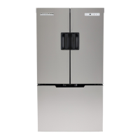
Specific steps for models with ice maker or dispenser.
Procedure for removing the refrigerator and cooling unit.
Specific steps for ice maker/dispenser models.
Steps for installing a new cooling unit.
Warning against using non-approved sealants.
Guidance on correct sealant application.
Important note regarding sealant application for optimal performance.
Warning about damaged combustion seals and LP gas exhaust.
Specific steps for ice maker/dispenser models during reinstallation.
Description and location of the power board.
Step-by-step procedure for removing the power board.
Step-by-step procedure for installing the power board.
Important note regarding AC heater wire connections.
Specific steps for ice maker/dispenser units during power board service.
Function of the temperature setting switch.
Description of the display showing mode, faults, and info.
Function of the power switch for turning the unit on/off.
Function of the mode switch for selecting operation modes.
Description of the control assembly interface.
Procedure for replacing the optical control assembly.
Explanation of the AUTO mode's heat source selection.
Details on how AUTO AC operation works.
Information on momentarily displaying the heat source in use.
Details on how AUTO LP operation works when AC is unavailable.
How the controls shift from LP to AC mode.
Troubleshooting steps for no AC power and no flame.
Information on 'gas lock-out' clearing.
References for correcting ignition and 'no AC' faults.
Procedure to access the diagnostic mode.
Instructions on how to navigate through diagnostic screens.
Procedure to exit the diagnostic mode.
Verifies LED screen and light operational status.
Confirms reliability of display segments and lights.
Displays real-time activity of the refrigerator.
Displays real-time activity of the refrigerator.
Shows stored fault history using LED lights.
Shows stored fault history using LED lights.
Displays actual fin temperature sensed by the thermistor.
Shows AC heater current measured by the controls.
Displays AC input voltage measured by the controls.
Displays DC voltage measured by the controls.
Procedure to access the diagnostic mode.
Instructions on how to navigate through diagnostic screens.
Procedure to exit the diagnostic mode.
Confirms diagnostic mode is active and LEDs are lit.
Checks reliability of display segments; lights should be off.
Displays fin temperature sensed by the thermistor.
Shows stored fault history using LED segments.
Shows stored fault history using LED segments.
Procedure to erase fault history from memory.
Displays live power board inputs using LED segments.
Shows DC voltage status and assigned LED segments.
Displays live power board outputs using LED segments.
Shows AC voltage status and assigned LED segments.
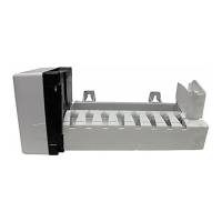
Details ice maker cycle, capacity, and electrical ratings.
Description of the ice maker wire harness connections.
Note on saving screws and components during replacement.
Procedure for installing a replacement ice maker.
Warning about turning the water fill adjustment screw.
| Type | Absorption Refrigerator |
|---|---|
| Interior Light | Yes |
| Refrigerant | Ammonia |
| Power Source | AC, DC, LP Gas |
| Capacity | 12 cubic feet |