

C
Carl LopezJul 27, 2025
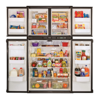
Why does my Norcold Water Dispenser water have a bad taste?
- MMatthew GrimesJul 27, 2025
If the water from your Norcold Water Dispenser has an odor or bad taste, the following could be the reason: - The vehicle water filter may need to be replaced or installed. - The vehicle water system may need to be sanitized. - The dispenser reservoir may need to be purged by running out several glasses of water.