10
www.norcold.com
2118, 2118IM, 2118IMD Series
from the enclosure to test the thermostatic
switch. If the vehicle has an upper side-
wall exhaust vent, you are able to test the
thermostatic switch by removing the upper
sidewall vent.
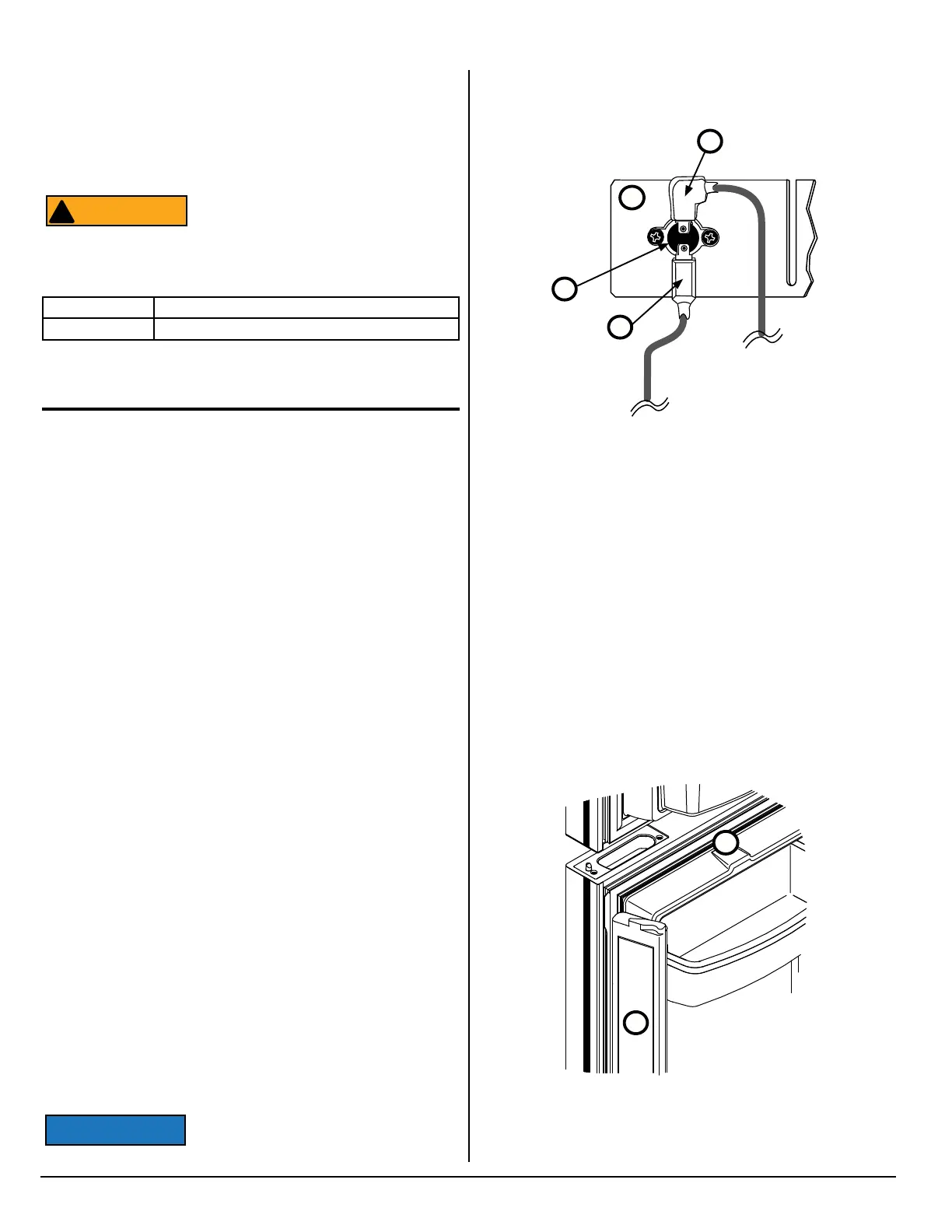
Movable Door Seal
The apper assembly [324] (See Fig. 8) is hinged onto the left hand
door [10] of the fresh food compartment. The apper assembly pro-
vides the vertical sealing surface between the fresh food compart-
ment doors for their inboard gaskets.
The apper is equipped with a 12 volt DC moisture reduction
heater. The heater is supplied power through a wire harness
foamed into the door.
The heater is turned on when spring pins, on the hinge side of the
door, make contact with the permanent contacts that are in the side
of the refrigerator cabinet. The left hand fresh food compartment
door must be fully closed to close the connection. Powering on the
refrigerator automatically energizes the apper heater circuit.
Verify that the heater is operating by touching the exterior sur-
Electrical Connections, cont’d.
Electrical Components
Fresh Food Compartment Light
The fresh food compartment light is turned on and off by door
operated switches. Each switch is located in the top of fresh food
compartment above each door.
Divider Heater
The divider heater is permanently “foamed into” the divider be-
tween the freezer compartment and the fresh food compartment.
The divider heater warms this area to prevent condensation from
forming. Powering on the refrigerator automatically powers on the
divider heater. Power to the heater is continuously supplied by the
power board.
12 Volt DC Fans
12 volt DC fans increase ventilation of the cooling system. Two (2)
larger fans are located near the condenser on the rear of the cool-
ing system foam plug. The third smaller fan is located below the
absorber coils of the cooling system.
All of the fans are unidirectional. The larger fans each draw 0.430
amps @ 12 volts DC. The smaller fan draws 0.140 amps @ 12
volts DC. Fan resistance through the fan motor circuit is approxi-
mately 1.8 ohms.
The fans are controlled by a thermostatic switch.
Thermostatic Switch
The thermostatic switch [321] is located on the rst condenser n
[10] (See Fig. 7). Incoming +12 volt DC [322] is fed through the up-
per terminal of the thermostatic switch. The +12 volt DC out [323]
connects to the lower terminal of the thermostatic switch.
The switch turns the fans on and off. The fans come on when the
temperature of the rst condenser n is about 130° F (54.4° C) and
turn off at about 115° F (46°C).
If the vehicle has a roof exhaust vent,
you may need to remove the refrigerator
Fig. 7 - Thermostatic switch for fans.
NOR000202A
10
322
321
323
■ Use a minimum of 18AWG wire for supply wire and maximum 6
A in-line fuse for the DC power supply wires.
■ Make sure an in-line fuse is installed on the DC positive wire,
as near the battery as possible, between the battery and the
terminal block of the refrigerator.
This in-line fuse is necessary for added
safety, even though the refrigerator has a
DC fuse in the control assembly.
Replacement Fuse Size
AC circuit AGC Series, Fast Acting,Glass Tube (1/4 in.x 1 -1/4 in.)
DC circuit Automotive Blade, Type APR-5A-Tan
ATTENTION
!
Fig. 8 - Movable door seal.
324
Art01813
10