SERVICE MANUAL
15
www.norcold.com
Fault Codes
Blank Display
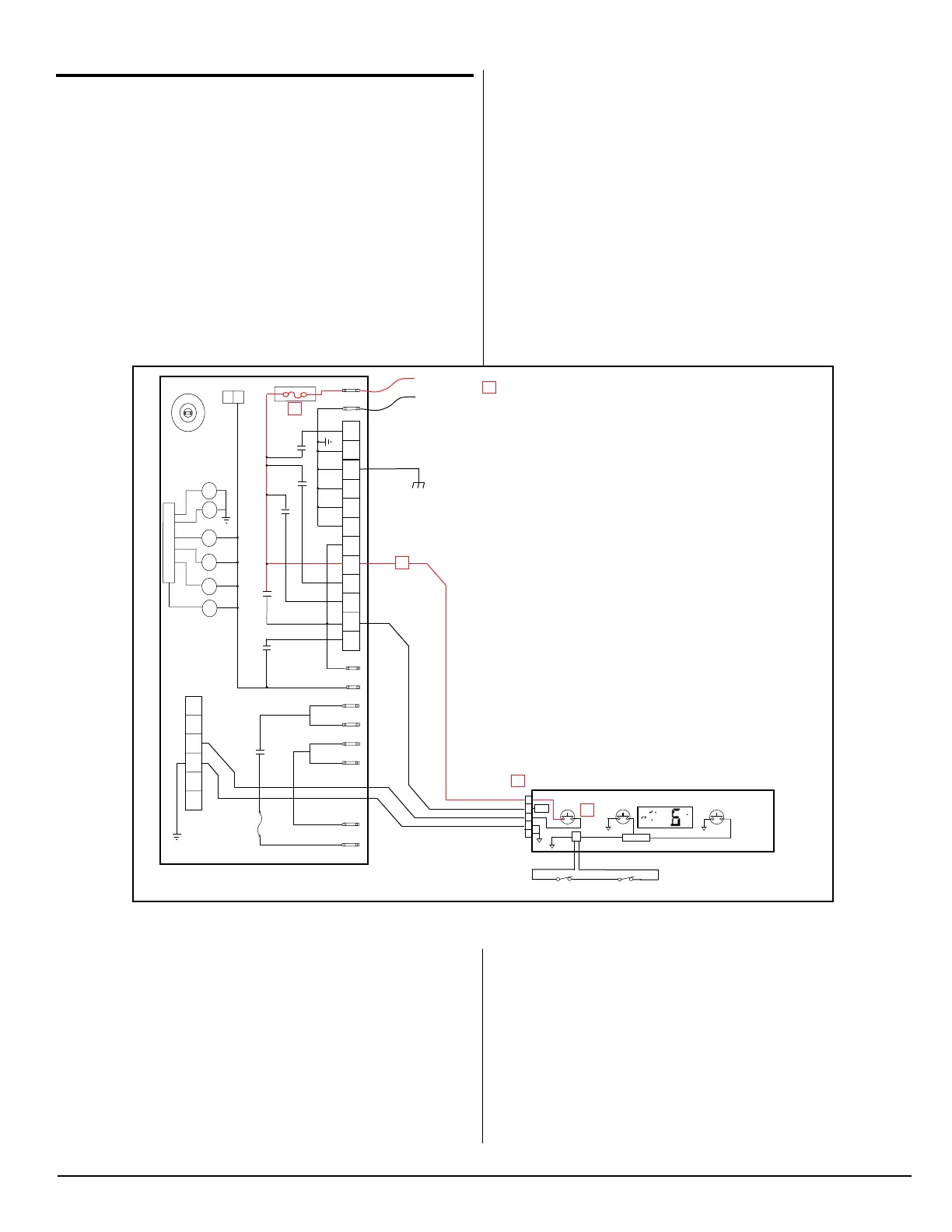
On-Off Theory of Operation:
Continuous 12-Volts (See Fig.14)
12VDC is supplied to the refrigerator at Power Board terminals
12VDC & GND [A]. This 12VDC travels through the Power Board
to fuse F1 [B] and then out to P1-6 [C]. Via the red-blue wire, the
12VDC exits the Power Board and enters the Display Board at
P1-1 [D]. The 12VDC travels through the Display Board to one side
of the normally open On-Off switch [E]. This 12VDC is referred
to as the continuous 12-volts because it is always present at the
one side of the On-Off switch when 12VDC power is applied to the
refrigerator.
Fig. 14 - Continuous 12 Volts
NOR000240A
12VDC
GND
LIMIT_OUT
LIMIT_IN
AC_HT_HI_2
AC_HT_HI
AC_HT_LO
AC_HT_LO_2
L1
L2
4
1
2
35
6
125
3
4
67
8
9
10
1
2
K2
K5
K3
K1
K4
F2 8-Amp
F1 5-Amp
-
+
P3
-
-
-
+
+
+
+
+
P2
P1
+
U1
K2
K5
K4
K3
K1
YL-GN/JN-VE
RD-YL/RG-JN
BK-NR
RD-BU/RG-BL
POWER BOARD/PANNEAUD’ALMENTATION
WH-BK/BC-NR
TEMP
ON-OFF
MODE
MICRO
Vreg
1
2
3
4
5
P1
P3
DISPLAY BOARD /
CARTE D’AFFICHAGE
C
B
D
A
E
BK-NR
BU-BL
BU-BL
RD-YL/RG-JN
12
P4
12VDC/VCD (BAT POS)
12VDC/VCD (BAT NEG)
K6
K6
Switched 12-Volts (See Fig. 15):
Pressing the On-Off switch [E] will allow 12VDC to pass through
the On-Off switch and back to the Power Board via the blue wire [F]
connected between the Display Board at P1-3 [G] and the Power
Board at P2-3 [H]. Once the 12VDC reaches the Power Board, a
signal is sent out to the coil of relay K3 [J] via the U1 microproces-
sor. This signal allows the K3 relay to energize thus closing the
normally open contacts [K].