30
www.norcold.com
2118, 2118IM, 2118IMD Series
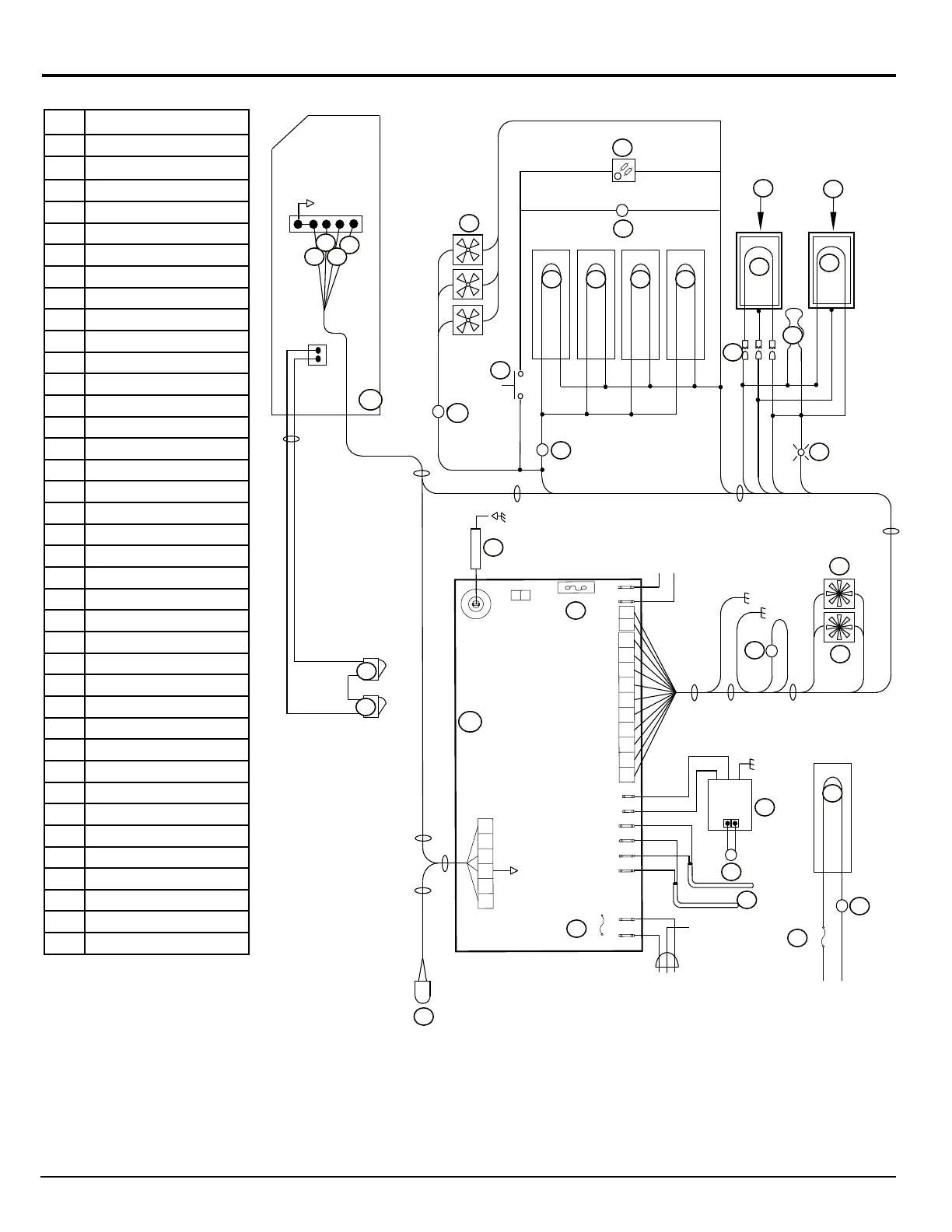
Description
PB Power Board
DB Display Board
A AC Heaters
B Light
C Thermistor
D Gas Valve
E Divider Heater
F Perimeter Heater
G Fresh Food Blower
H Temperature Monitor Control
I External Fans
J * Ice Maker Water Line Heater
K * Water Valve Heater
L * Dispenser Water Line Heater
M * Dispenser Water Valve Heater
N * Water Valve
O * Dispenser Light P.C.B.
P * Dispenser Switch
Q Temperature Switch
R * Temperature Switch
S Divider Heater Housing
T Door Contacts
U Flapper Heater
V Flapper Housing
W Door Switch
X Igniter
Y Freezer Blower
Z Thermocouple
1 Fused Continuous 12 VDC
2 Switched 12 VDC
3 Communications
4 Display Ground
11 Cooling Unit Heater
12 Temperature Switch
F1 5 Amp DC fuse
F2 8 Amp AC fuse
F3 3 Amp DC fuse
* Optional
Wiring Pictorial
Fig. 18 - Wiring Pictorial
12VDC
GND
LIMIT_OUT
LIMIT_IN
AC_HT_HI_2
AC_HT_HI
AC_HT_LO
AC_HT_LO_2
L1
L2
4
1
2
35
6
125
3
4
67
8
9
10
1
2
F2 8-Amp
F1 5-Amp
P3
P2
P1
PB
2
1
P4
T1
+12V IN
+12V OUT
GND
+
-
YL/JN
RD/RG
Z
W
DB
B
A
H
G
D
C
T
X
Y
P1-4
P1-2
P1-6
P1-9
P1-3
P1-1
P1-10
P4-1
P4-2
U
F
E
V
S
P1-8
N
M
L
K
J
I
P
O
Q
R
P1-7
P1-5
GND
GND
P2-6
P2-1
P2-3
P2-4
W
P1-1
P1-6
4
3
2
1
11
F3 3-Amp
+12VDC / +12VCC
12VDC GND / -12VCC
+12VDC / +12VCC
12VDC GROUND / -12VCC
P3-1
P3-2
12
P1-5
2
4
2
5
7
9 11
12
2
2
4
NOR000187A
A
B
C
E
F
G
H
I
J* K* L*
M*
N*
O*
P*
Q
R*
S
T
U
V
W
W
X
Y
Z
1
2
3
4
11
12
F3
F2
F1
DB
PB
+12VDC
12VDC GROUND
D
+12VDC
12VDC GROUND