SERVICE MANUAL
27
www.norcold.com
1 Food compartment light is off and door is closed.
2 Flame is sensed.
3 Thermistor is sensing fin temperature.
4 Not used.
5 Not used.
6 Not used.
7 Not used.
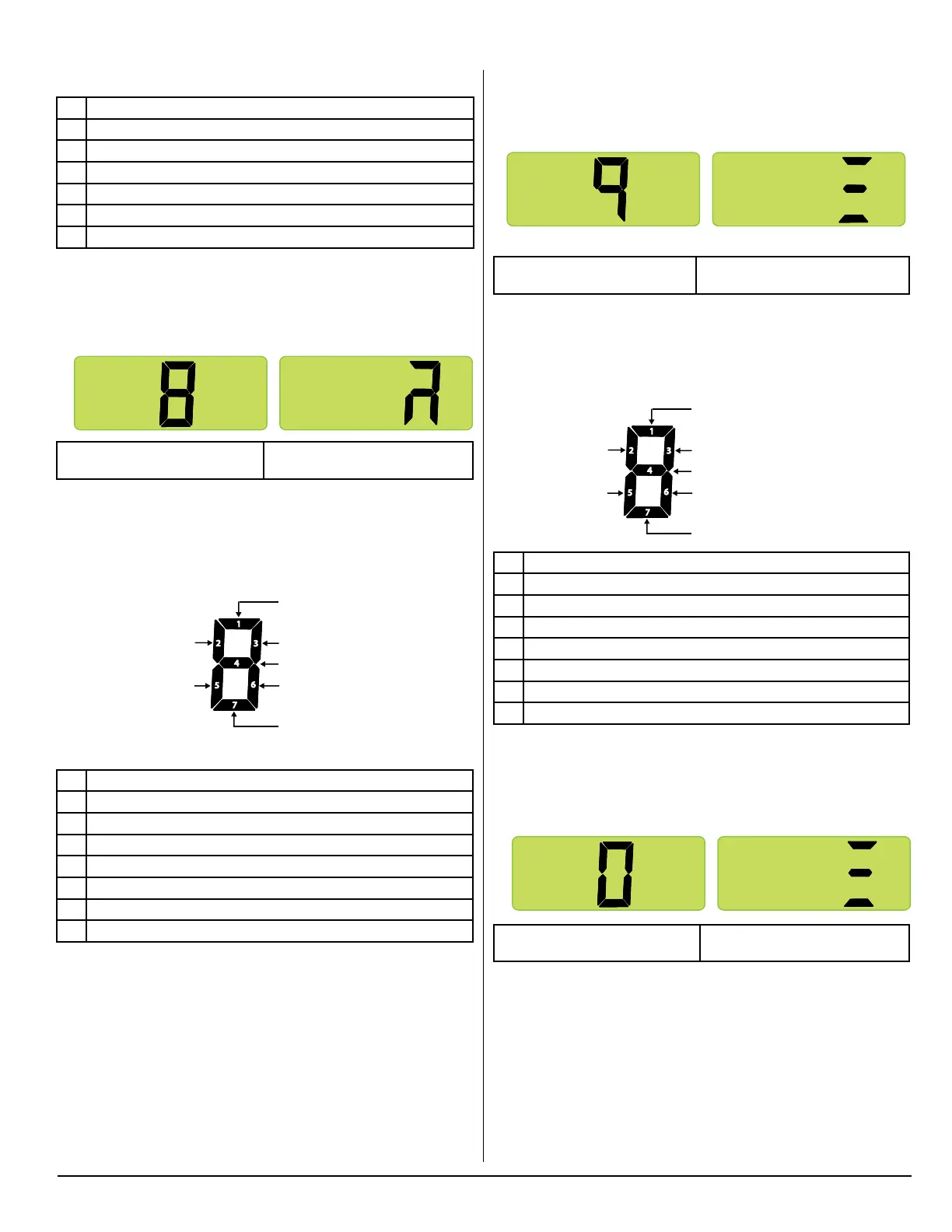
Screen 8. Power Board Outputs
Press the MODE button to bring up screen 8.
Screen 8 (Initial view) Screen 8 (Second view)
All segments shown as being on
Screen 8 displays “live” power board outputs using lighted LED
segments. The following illustration provides denitions of the
“live” outputs indicated by the individual LED segments. If a power
board output is active or “live,” its assigned output LED seg-
ment will be on.
Individual Segment Identification
1 AC heater relay is energized.
2 Not used.
3 DC power to divider heater.
4 Gas valve relay is energized.
5 DC power to light switch.
6 DC power to ignition circuit.
7 Not used.
Diagnostic Mode, cont’d.
Diagnostic Screen 8 (Initial View) Diagnostic Screen 8 (Second View)
1
2
3
5
6
7
4
Not used
DC power to
light switch
AC heater relay is energized
DC power to divider heater
Gas valve relay is energized
DC power to ignition circuit
Not used
NOR000125A-8
Diagnostic Screen 8 (Initial View) Diagnostic Screen 8 (Second View)
1
2
3
5
6
7
4
Not used
DC power to
light switch
AC heater relay is energized
DC power to divider heater
Gas valve relay is energized
DC power to ignition circuit
Not used
Screen 9. Power Board DC Input Voltage Status
Press the MODE button to bring up screen 9.
Screen 9 (Initial view) Screen 9 (Second view)
All segments shown as being on
Screen 9 displays DC voltage status using lighted LED segments.
Refer to illustration below for denitions of the individual LED seg-
ments. If DC voltage at the power board is within normal range
(10.5 to 15.4 VDC), LED segment 4 will be on.
Individual Segment Identification
1 DC voltage higher than 15.4 volts.
2 Not used.
3 Not used.
4 DC voltage normal.
5 Not used.
6 Not used.
7 DC voltage lower than 10.5 volts.
Screen 0. Power Board AC Input Voltage Status
Press the MODE button to bring up screen 0.
Screen 0 (Initial view) Screen 0 (Second view)
All segments shown as being on
Screen 0 displays AC voltage status using lighted LED segments.
Refer to illustration below for denitions of the individual LED seg-
ments.
Diagnostic Screen 9 (Initial View) Diagnostic Screen 9 (Second View)
1
2
3
5
6
7
4
Not used
Not used
DC voltage higher than 15.4 volts
Not used
DC voltage normal
Not used
DC voltage lower than 10.5 volts
NOR000125A-9
Diagnostic Screen 9 (Initial View) Diagnostic Screen 9 (Second View)
1
2
3
5
6
7
4
Not used
Not used
DC voltage higher than 15.4 volts
Not used
DC voltage normal
Not used
DC voltage lower than 10.5 volts
Diagnostic Screen 9 (Initial View) Diagnostic Screen 9 (Second View)
1
2
3
5
6
7
4
Not used
Not used
AC voltage higher than 132 volts
Not used
AC voltage normal
Not used
AC voltage lower than 85 volts
NOR000125A-0