This document is a service manual for Norcold DCXXXX and DEXXXX model compressor refrigerators. It provides detailed troubleshooting procedures, technical specifications, and maintenance information for various models, including DC0040(K), DC0051(K), DE0040, DE0051, DE0240T, DE0251T, DC0740(X), DE0740(X), DC0751(X), and DE0751(X). The "X" in the model numbers indicates the equipment color, which can be "B" (black), "S" (stainless steel), or "W" (wrapped door - stainless steel).
Function Description:
The Norcold DCXXXX and DEXXXX series refrigerators are compressor-based cooling units designed for various applications, likely including RVs, marine vessels, or off-grid setups, given the emphasis on DC power and ventilation. These refrigerators utilize a compressor to circulate refrigerant and provide cooling. They are equipped with a temperature control system, a power supply that can handle both DC (10.5-32V) and AC (85-132V) input, and safety features like an auto shut-off device for overheating protection. The manual outlines how to diagnose and resolve issues related to the compressor, power supply, thermistor, and cooling performance.
Important Technical Specifications:
- Power Input: The refrigerators are designed to operate on both DC and AC power.
- DC Voltage Range: 10.5V to 32V DC.
- AC Voltage Range: 85V to 132V AC.
- Compressor Power Consumption:
- 40 Watt Compressor:
- Normal Amp Draw: 1.6 – 2.0 Amps (at 12.8V DC).
- Failure Threshold: > 2.0 Amps.
- 60 Watt Compressor:
- Normal Amp Draw: 2.7 – 3.3 Amps (at 12.8V DC).
- Failure Threshold: > 3.3 Amps.
- Compressor Resistance: The resistance between points A and B at the compressor should be between 1.4 – 3.5 Ω at room temperature. A reading of 0 Ω or ∞ Ω indicates an internal compressor failure.
- AC Power Supply Output Voltage: When operating on AC, the power supply output to the compressor should be between 15V and 25V AC. The AC power supply itself requires 37-45V DC input (as measured in Figure 5).
- DC Power Supply Output Voltage: The DC power supply output to the compressor is not explicitly stated as a single value but is part of the overall DC operation.
- Fuses: A 10 Amp fuse is used in the DC input circuit. If blown, vehicle wiring should be checked.
- Evaporator Thermistor Resistance: The thermistor's resistance varies with temperature and is critical for proper operation.
- General Good Range: 1.6K - 29KΩ.
- Specific values provided in Table 1 (Evaporator Thermistor Resistance):
- 0°F (-18°C): 9.7 KΩ (Allowable Range: 8.7 - 10.7 KΩ)
- 10°F (-12°C): 7.8 KΩ (Allowable Range: 7.0 - 8.6 KΩ)
- 20°F (-7°C): 6.4 KΩ (Allowable Range: 5.7 - 7.0 KΩ)
- 30°F (-1°C): 5.3 KΩ (Allowable Range: 4.8 - 5.7 KΩ)
- 40°F (4°C): 4.5 KΩ (Allowable Range: 4.0 - 4.9 KΩ)
- 50°F (10°C): 3.6 KΩ (Allowable Range: 3.2 - 4.0 KΩ)
- 60°F (16°C): 2.8 KΩ (Allowable Range: 2.5 - 3.1 KΩ)
- 70°F (21°C): 2.1 KΩ (Allowable Range: 1.9 - 2.3 KΩ)
- 80°F (27°C): 1.9 KΩ (Allowable Range: 1.7 - 2.0 KΩ)
- 90°F (32°C): 1.8 KΩ (Allowable Range: 1.6 - 1.9 KΩ)
- An ∞ Ω reading indicates a defective (open) thermistor, which will stop normal compressor operation.
- Fan Voltage: The operational voltage of the fan is between 17V and 22V DC.
- Auto Shut-Off Device Trigger Temperature: Approximately 110°F (43°C) ambient air temperature.
Usage Features:
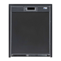
- Temperature Control: The refrigerator features a temperature control knob, with "Off" as the starting position, and settings from 1 (warmest) to 5 (coldest).
- Auto Shut-Off Device: Only available on 12/24V DC and DE/Truck models. This safety feature protects the cooling unit from overheating by automatically shutting off the refrigerator if the ambient air temperature reaches approximately 110°F (43°C). An intermittent alarm tone will sound when shut-off occurs.
- Restarting After Shut-Off: To stop the alarm and restart the refrigerator after an auto shut-off, turn the temperature control counterclockwise to "Off" and then to the desired setting. The refrigerator will only restart once ambient conditions allow for normal operation.
- Ventilation: The refrigerator incorporates built-in ventilation systems. Cooler air is drawn through a lower intake vent, circulated over the cooling unit to remove excess heat, and then rejected through an upper vent. Proper ventilation is crucial for correct operation, increased lifespan, and efficient cooling.
Maintenance Features:
- Troubleshooting Procedures: The manual provides nine detailed troubleshooting procedures (A through I) covering common issues such as:
- Compressor not running.
- Compressor resistance measurement.
- Power supply output voltage checks.
- Compressor amp draw measurement.
- Thermistor operation verification.
- Insufficient cooling.
- Refrigerator being too cold.
- Auto shut-off device operation.
- Proper ventilation.
- Quick Reference Troubleshooting Steps: A condensed guide for initial diagnosis, including checks for supply voltage, compressor voltage, compressor Ohm reading, and compressor Amp draw.
- Component Replacement Guidance: The manual guides users on when to replace specific components like the DC power supply, AC power supply, cooling unit, 10A fuse, or thermistor based on diagnostic results.
- Ventilation Importance: Emphasizes the need for proper ventilation to prevent shortened cooling unit life, poor cooling performance, continuous operation, and fast battery discharge, which can also void the warranty. Users are cautioned not to block the vents.
- Testing the Shut-Off Device: Instructions are provided to test the auto shut-off device's functionality by heating it with a heat gun.
- Fan Servicing Caution: Warns against shorting the fan wires during servicing, as this can damage the power supply.
- Diagnostic Tools: The procedures require the use of a multimeter for measuring voltage, resistance (Ohms), and amperage.
- Power Source for Testing: A critical warning advises performing all tests using a fully charged 12V DC battery, as using other DC voltage supply equipment may cause permanent refrigerator component failure.