Do you have a question about the nord NORDAC SK 500E and is the answer not in the manual?
| Protection class | IP20 |
|---|---|
| Overload capacity | 150 % for 60 s |
| Braking resistor | Optional |
| Efficiency | Up to 98% |
| Mounting | Wall mounting |
| Control | Vector control |
| Communication | CANopen, EtherCAT, EtherNet/IP, Modbus RTU |
| Frequency | 0 to 400 Hz |
| Protection | Overcurrent, overvoltage, undervoltage, overtemperature |
| Series | NORDAC SK 500E |
| Supply voltage | 3 x 400/480 V AC |
| Input Voltage | 3 x 400/480 V AC |
General safety and operating guidelines for drive power converters.
General safety instructions and personnel qualifications.
Installation requirements and protection against impermissible loads.
Safety regulations for electrical connections and EMC-compliant installation.
Requirements for systems with drive power converters and operation safety.
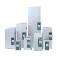
Describes the properties and features of the basic SK 500E device and its variants.
Crucial safety precautions and installation guidelines for high-voltage systems.
Explains the structure of the NORDAC SK 500E type code and device design.
Details the installation requirements, including ventilation and mounting position.
Provides housing and wall-mounting dimensions for the SK 500E standard version.
Details mounting dimensions for the SK 500E standard version, including wall mounting.
Explains the use and components of the optional EMC Kit for optimum wiring.
Provides essential guidelines for EMC-compliant wiring of frequency inverters.
Details the electrical connection of the power unit, including mains supply and motor terminals.
Covers electrical connections for the control unit, including terminal blocks and cable cross-sections.
Details the terminal blocks for size 1 to 4 devices, including connections and DIP switch functions.
Details color and contact assignments for incremental encoders, with recommendations.
Describes the RJ45 WAGO connection module for simple cabling of RJ45 functions.
Provides an overview of available technology units for parameterisation and control.
Details the SimpleBox as a tool for parameterisation, display, and control of the frequency inverter.
Describes the ControlBox for parameterisation, display, and direct control of the frequency inverter.
Details the ParameterBox for parameterisation, control, and display of inverter settings.
Explains how to set factory parameters and input motor data.
Details the minimum circuitry and basic parameters for immediate control via digital/analog inputs.
Explains the connection and parameter settings for the KTY84-130 temperature sensor.
Explains how to display operating parameters and status on SimpleBox or ControlBox.
Covers essential basic parameters for inverter setup, including parameter sets and acceleration/deceleration times.
Details parameters for configuring motor data and characteristic curves for optimal performance.
Details control parameters related to incremental encoders for SK 520E/530E.
Details the functions and settings for analog inputs used for control.
Details additional parameters for leading function value and output, pulse frequency.
Details parameters for positioning control, specific to SK 53xE frequency inverters.
Provides information on current and historical faults, including frequency, current, and voltage.
Provides an overview of parameters and their factory settings for monitoring and user adjustments.
Describes how errors are displayed on SimpleBox/ControlBox and how to acknowledge them.
Provides a comprehensive table of error messages, causes, and remedies.
Details general specifications including output frequency, overload capacity, and interfaces.
Lists electrical data for 115V SK 5xxE devices, including motor power and fuses.
Lists electrical data for 230V SK 5xxE devices, covering various sizes and phases.
Provides electrical data for 400V SK 5xxE devices, including current and fuse recommendations.
Details electrical data required to comply with UL certification standards.
Explains conditions and requirements for using ColdPlate technology, including thermal resistance.
Illustrates how setpoints are processed from various sources and through different functions.
Explains the PI process controller for limiting output and controlling downstream drives.
Explains EMC requirements, compliance methods, and operating classes for frequency inverters.
Explains factors that reduce output power, such as frequency and temperature.
Covers maintenance requirements, contact information for technical support, and repair procedures.
Lists NORD subsidiaries and offices worldwide for sales and support.