Do you have a question about the nord NORDAC PRO SK 500E Series and is the answer not in the manual?
General safety precautions and guidelines for device handling.
Guidelines for using devices within European electrical systems and ensuring compliance with EC directives.
Instructions for safe transportation, storage, and handling of the devices.
Requirements for equipment installation and cooling according to regulations.
Guidelines for electrical connection, including national accident prevention and EMC regulations.
Requirements for safe operation, including monitoring and protective equipment.
Information on maintenance procedures, including safety precautions for live components.
Emphasizes the necessity of following operating instructions for fault-free operation and warranty claims.
Describes the intended use of SK 500E series inverters for industrial and commercial systems.
Details the intended use of SK 5xxE inverters for stationary installation in control cabinets.
Outlines conditions for commissioning, including EMC and Machinery Directive compliance.
Details the first issue of the manual with version V 2.0 R5.
Describes revisions including general corrections, parameter adaptations, and section updates.
Details updates including standards, declaration of conformity, and energy efficiency levels.
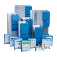
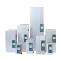
Provides an overview of the basic frequency inverter SK 500E properties.
Explains the differences between SK 5xxE types with and without integrated mains filters.
Guides the selection between "-A" and "-O" inverter types based on mains supply conditions.
Instructions for checking equipment immediately after delivery for transport damage.
Lists the standard version components and included items.
Essential safety and installation guidelines for proper and safe operation.
Lists the standards and directives with which the devices comply.
Details the categorisation of protective devices approved by UL.
Describes the standard mounting procedure for frequency inverters directly on a control cabinet wall.
Explains the use of ColdPlate versions for effective heat dissipation without a fan.
Describes the external heat sink kit as an optional supplement for ColdPlate devices.
Details the kit for mounting inverters on standard TS35 mounting rails.
Explains the use of the optional EMC Kit for optimum EMC-compliant wiring.
Information on external brake resistors used for preventing inverter shutdown due to overvoltage.
Provides electrical data for SK BR2- and SK BR4- brake resistors.
Explains the purpose of chokes for mains protection and reducing motor effects.
Describes additional external line filters for maintaining noise suppression levels.
Details all electrical connections, including mains, motor, and control connections.
Provides general instructions for wiring to ensure safe and interference-free operation.
Explains how to adapt the inverter for operation in IT networks using jumpers or DIP switches.
Discusses criteria and considerations for setting up DC supply or coupling link circuits.
Provides information on all power connections to the frequency inverter.
Details the control connections located under the front cover of the frequency inverter.
Explains the colour coding and contact assignments for connecting encoders.
Describes the adapter module for simplifying wiring of RJ45 connections.
Explains how SK 5xxE can be adapted using modules for display, control, and parameterisation.
Provides an overview of available technology units and control boxes for different functions.
Details the pre-programmed default settings for standard applications and motor data input.
Explains the different operating modes for motor control, applicable to all efficiency classes.
Describes various operating modes like VFC, CFC open-loop, and CFC closed-loop.
Provides an overview of important parameters for selected operating modes.
Lists the crucial steps for commissioning motor control, including connections and parameter settings.
Outlines the minimal connections required for controlling the inverter via digital and analog inputs.
Details the connection and parameter settings for the KTY84-130 temperature sensor.
Explains how to add or subtract values using operating boxes with specific software versions.
Explains that parameters are subject to conditions and provides tables listing them.
Describes the selection of physical units for the display value.
Details how to select the operating display for parameterisation boxes.
Explains the selection of parameter sets and how they are managed.
Defines the start-up time for linear frequency rise.
Specifies the minimum frequency supplied by the FI when enabled.
Defines the frequency supplied by the FI once the maximum setpoint is present.
Enables smoothing of acceleration and deceleration ramps for dynamic speed changes.
Addresses the delayed reaction time of electromagnetic brakes.
Determines how the output frequency is reduced after "Blocking".
Sets the current for DC current braking and combined braking functions.
Sets the initial value for jog frequency following successful enabling.
Allows changing factory settings for motor data and selecting standard motors.
Determines the V/f break point at which nominal voltage is supplied.
Defines the stator resistance, influencing current control and torque.
Automatically matches motor flux to motor load for energy saving.
Allows automatic determination of motor data for devices up to 7.5 kW.
Defines the control method for the motor, offering different levels of dynamics and precision.
Input for the pulse count per rotation of the connected encoder.
P-component of the speed controller for proportional amplification.
Current controller for the field current.
Determines at which speed/current the controller begins to weaken the field.
Defines the regulation method for PMSM motors at speed n<nSWITHOVER.
Used for determining the starting position of the rotor relative to the universal encoder.
Configures digital inputs to process analog signals.
Determines how the frequency inverter reacts to an analog signal.
Sets the voltage corresponding to the minimum value of the selected analog function.
Adjustable low-pass filter for the analogue signal.
Defines the minimum frequency that can act on the setpoint via auxiliary setpoints.
Fixed specification of a setpoint for the process controller.
P-component of the PID controller for frequency actual frequency selection.
Enters an offset to simplify analog signal processing in other equipment.
Sets the analog outputs of the FI or connected IO extension module.
Adjusts the limiting values of analog output for the selected working range.
Configures digital inputs to process analog signals.
Details the functions that can be assigned to digital inputs.
Sets the stop time for the fast stop function.
Activates automatic emergency stop following an error.
Sets a fixed frequency used as a setpoint after actuation via digital input.
Details the functions that can be assigned to relay and digital outputs.
Adjusts the limiting values of digital functions.
Activates speed control by HTL encoder.
Determines how fixed frequencies are processed.
Perceives Bus I/O In Bits as digital inputs for function assignment.
Defines simple, logical sequences of functions using triggers and responses.
Allows free input of a designation for unique device identification.
Specifies the bus system via which the master transmits control word and master values.
Allows changing the internal pulse frequency for controlling the power unit.
Specifies the frequency value that cannot be undershot by the FI.
Selects automatic error acknowledgement.
Parameter for technology units Profibus, DeviceNet, or InterBus.
Sets the transfer rate for the CANbus interface.
The output frequency around this value is not shown.
Required to connect the FI to already rotating motors.
Loads factory settings for all parameters.
Motor current monitoring based on I2t values.
Monitors the quality of the power supply.
Controls relay and digital outputs independently of inverter status.
Selects the return value for bus actuation.
Allocates a function to the setpoint during bus actuation.
Assigns the setpoint of the PotentiometerBox to a function.
Allows saving a data set from the connected FI to the ControlBox.
Activates relevant process data profiles based on the option.
Programs a manual peak power limit for the brake resistor.
Sets the magnetizing time for correct ISD control function.
Determines how parameter changes are saved.
Indicates the reason for the device being in "Not Ready" or "Start Disabled" status.
Generated when a defined limit is reached, without causing the inverter to switch off.
Errors cause the device to switch off to prevent faults.
Explains how device status is indicated by LEDs.
Lists and explains various fault and warning messages.
Provides general specifications for the SK 500E frequency inverter.
Contains electrical data relevant for UL approval.
Details electrical specifications for 115V devices.
Details electrical specifications for 230V devices, including single and three-phase connections.
Details electrical specifications for 400V devices, including three-phase connections.
Outlines conditions and data for devices utilizing ColdPlate technology.
Illustrates how setpoint processing is handled for SK 500E...SK 535E devices.
Explains the PI controller for limiting controller output and scaling.
Covers EMC directive requirements and evaluation standards.
Explains circumstances leading to reduced output power and provides characteristic curves.
Discusses operation with 30mA all-current sensitive FI circuit breakers.
Highlights the high efficiency of NORD frequency inverters and the role of automatic flux optimisation.
Provides details for standardizing typical setpoint and actual values.
Explains how frequencies are processed according to setpoint and actual value parameters.
Provides guidelines for maintenance, including cleaning and long-term storage.
Offers information on contacting technical support and the repair process.
Lists common abbreviations used throughout the manual.