11
GB
outlet and roof of infl ammable material must be at
least 500 mm. The distance from the front of the insert
to furniture needs to be of at least 1 metre. When
connecting a steel chimney to the top outlet use the
security distances required from the manufacturer.
Important! When placing the insert on a
combustible fl oor, a steel plate of at least 0.7mm
must cover the entire fl oor surface inside the
surround. Any fl ooring made of combustible
material, such as linoleum, carpets etc. must be
removed from underneath the steel plate.
4. Assembly
The following tools are necessary:
13 mm spanner/wrench •
Electrical drill / Phillips screwdriver (for self drilling •
screws)
Caulking gun (for the stove cement)•
Possibly a hammer•
1. Ensure that you have all the loose parts (FIG 2):
Heat shield in two parts with 4 self drilling screwsA.
Lid for fl ue outlet with fastenersB.
Smoke domeC.
4 fasteners with bolts and disks for the domeD.
Insert with doorE.
3 bolts with disks for fastening the legsF.
3 legs, 3 adjusting bolts with nutsG.
Handle for air vent controlH.
Glove I.
The insert expands when in use, and for this
reason the insert must NEVER rest on the
surround, but have a gap of about 3 mm. The
insert must neither rest on the bench plate or
against the sides. It is recommended to dry
stack the surround in order to adjust the insert
prior to perforating the chimney for the fl ue
connection.
2. Carefully lay the insert on its back. Ensure that
the transportation padding is put inside the insert
before turning it over, so that the insulating plates
in the burn chamber do not fall down and break.
Please note that the insulating plates may release
coloured dust when touched. Avoid touching the
insert with dust on your fi ngers. Any visible dust on
the insert can be brushed off with the glove that is
included.
Start with assembling the legs (FIG 3) as follows:
•
Fasten the screws on to the insert with a 13 mm
spanner/wrench. The legs are placed as shown in
the illustration.
Use the adjusting bolts (FIG 4) and adjust the legs •
to the desired height (X) before returning the insert
to an upright position (do not tilt the insert). The
height depends on the surround.
Regulation of leg height (X) for N-21:
From: 210 mm To: 330 mm.
Floor under the fi replace
Ensure that the fl oor where the fi replace is placed
can withstand the load with regards to the total weight
of the fi replace. If unsure, contact the local building
authorities or a builder for review / approval. When
mounting the fi replace on a fl oating wooden fl oor, the
fl oorboards under the fi replace should be removed to
avoid that the fl oorboards lock and crack.
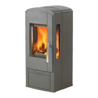
2. Technical Information
The inserts from Nordpeis have secondary
combustion and are clean burning. The combustion
takes place in two phases: fi rst the wood burns and
then the gases from the fumes are lit by the hot air.
This ensures that these new inserts have minimal
emissions of soot particles and unburnt gases (such
as CO) and are thus better for the environment. Clean
burning inserts require a small amount of wood in
order to obtain a good heat output. Use exclusively
clean and dry wood.
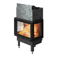
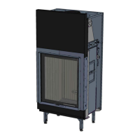
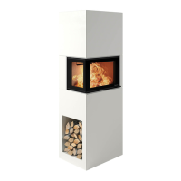
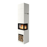
Insert: N-21
Material: Steel
Surface treatment
door/doorframe:
Heat resistant varnish
Fuel: Wood logs, 35 cm
Operating range: 2-10 kW
Draught system:
Ignition vent control and air
vent control
Combustion system:
Secondary combustion
(clean burning)
Heating area: 30-150 m²
Flue outlet: Top, posterior and lateral
Flue:
Inner Ø 150 mm
(NB! In UK outer Ø)
Weight of insert: 105 kg
Area of convection
air vent under insert:
280 cm²
Area of convection
air vent over insert:
480 cm²
Warning: If the requirements for ventilation are
NOT complied with, the heating circulation effect
will be considerably reduced and
overheating can occur.
This can in a worst case scenario cause a fi re.
3. Distance to Combustible Material
Ensure that the safety distances are respected
(FIG 1).
A The distance from the glass in the door to a lateral
wall, measured diagonally, must be of at least 800
mm.
The distance between the top of the convection air
 Loading...